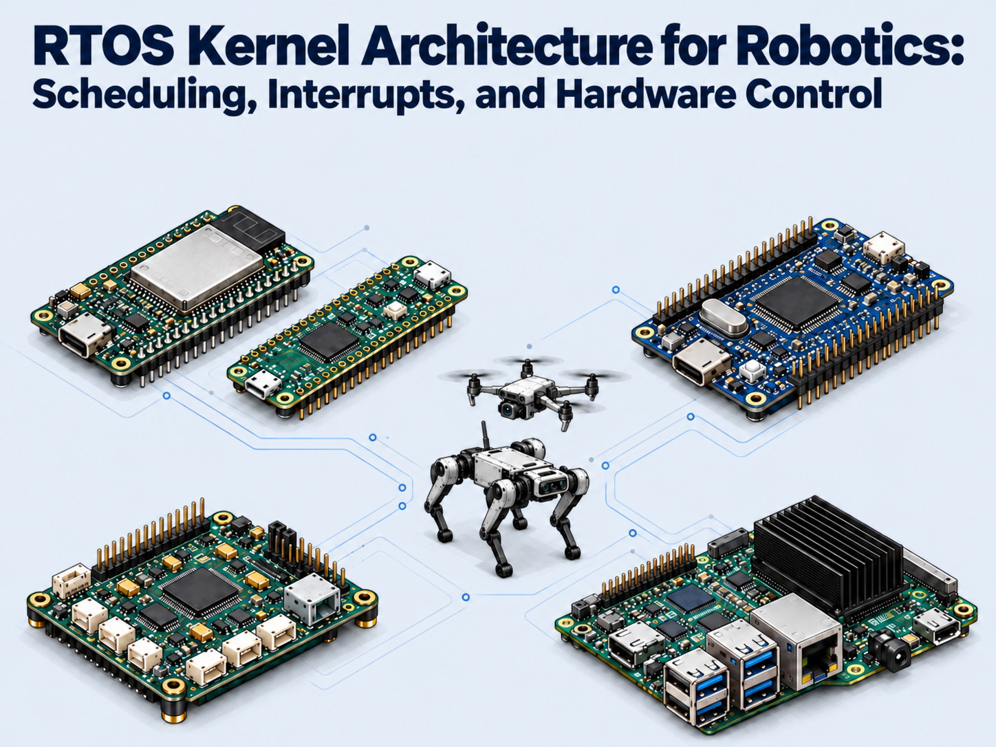
 FreeRTOS
ESP32 / STM32 / Pico & Pico 2 ↗
Zephyr
ESP32 / STM32 / nRF52840 ↗
NuttX / ChibiOS
Pixhawk 4
PX4 + NuttX / ArduPilot + ChibiOS ↗
Linux / PREEMPT_RT
Raspberry Pi 5 / Jetson Orin / Intel & AMD ↗
In this article
In this article
A robot needs the right command while that command can still help. A real-time operating system (RTOS) coordinates the work between sensing and actuation. Follow one joint correction through the RTOS architecture, from sensor input to hardware output.
1. The processor is fast. The robot still reacts too late.
A quadruped detects an uneven step and calculates the right correction
A quadruped steps onto a broken paving stone. An encoder reports a changed joint angle; the inertial measurement unit (IMU) detects the body rotating. The controller calculates a correction—but the robot keeps moving while that command travels to the joints.
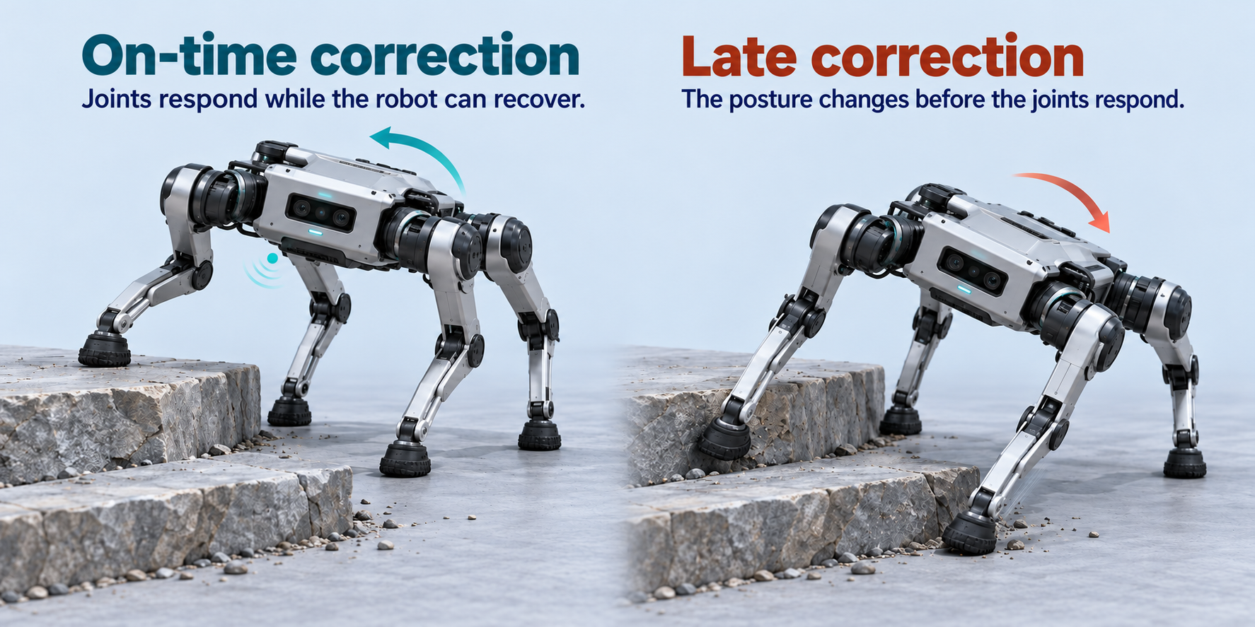
Correct arithmetic is only part of the job. A command based on an earlier posture may arrive after that posture has disappeared.
The correction reaches the joints after the robot needs it
Suppose this example requires the actuator command to be applied within 1 ms of the sensor sample. Computing the answer in 0.2 ms does not prove that the full response fits.
- Period
- Time between scheduled updates
- Deadline
- Latest acceptable completion
- Response time
- Sample to command application
- Jitter
- Variation in timing across updates
A fast average can hide occasional late updates. Real-time control requires sufficiently bounded and consistent timing across the complete path. The ROS 2 real-time background develops that distinction.
2. How the controller coordinates each step
How the CPU, memory and drivers turn sensor readings into joint commands
In microcontroller-based embedded systems, the CPU reads measurements, calculates a target, and calls a driver. The driver configures a peripheral; the peripheral delivers a signal to the actuator interface.
The robotics hardware guide explains how motors, transmissions, sensors, and joint loads shape that actuator interface.
- SensorIMU / encoderCapture a sample
- CPU + RAMControl taskCalculate target
- DriverRegister writesConfigure transfer
- PeripheralTimer / CANDeliver signal
- Joint drivePower stageApply command
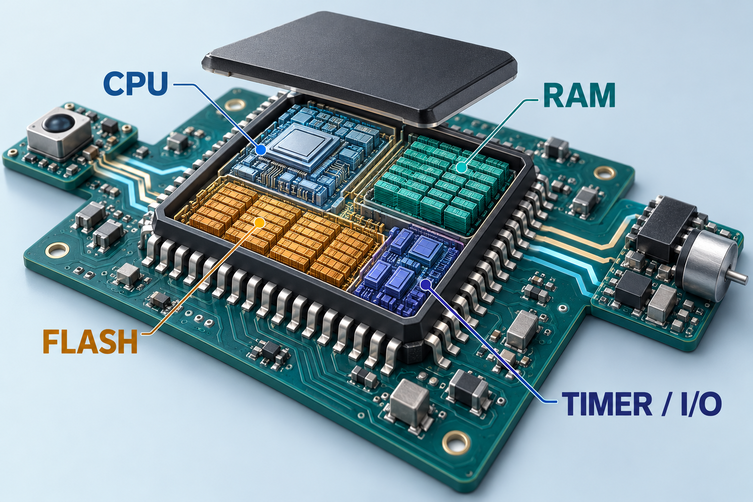
A PWM driver can write a timer’s compare register; the timer then generates pulses without the CPU toggling every edge. A bus driver instead prepares a transfer, sometimes assisted by DMA. Register write, transfer completion, and command application are different moments.
At instruction level, a memory-mapped register is an address decoded by the peripheral bus. A CPU store changes hardware state rather than an ordinary RAM variable. A timer may latch a new compare value only at its next update boundary; ST’s timer cookbook explains this preload mechanism. A CAN transfer must also wait for bus access. The drive then decides when to apply the command. These waits sit beyond task selection.
- 01CPU store
- 02Timer compare register
- 03PWM waveform
- 04Motor drive
A control pin carries a signal. The motor drive supplies operating power and may run its own faster current loop. The electronics behind physical AI follows that surrounding circuit and power path.
xTaskCreate()The configured allocator supplies its stack + TCB from the heap.
xTaskCreateStatic()The application supplies its stack array + TCB storage.
- Stack
- Local variables, calls + saved CPU context
- TCB · task control block
- Priority, list links + pointer to saved stack context
Each task needs RAM for its execution stack and its TCB. The stack holds function-call state and saved registers; the TCB tells the kernel where that context lives. A task’s stack is reserved storage, even when the task is Blocked.
xTaskCreate()xTaskCreateStatic()With upstream FreeRTOS, xTaskCreate() obtains the stack and TCB through the configured allocator. xTaskCreateStatic() accepts application-provided storage. Both still consume RAM; static creation removes the heap allocation for those objects. Stack depth uses StackType_t elements in upstream FreeRTOS, while ESP-IDF task-creation APIs use bytes. Check the task API
and IDF port differences
before copying a stack size.
That storage budget helps explain the platform split. A small FreeRTOS kernel and a Linux system carry different services; compare what each number includes before using it to select a chip.
| What is counted? | FreeRTOS reference | Embedded Linux reference |
|---|---|---|
| Kernel code / storage | ≈9–18 KBUsable kernel configurations, quoted by Richard Barry in 2022.FreeRTOS size discussion ↗ | ≈2–4 MBEmbedded kernel storage guidance in a 2017 Bootlin presentation.Bootlin kernel-size reference ↗ |
| RAM in a published example | 21,944 bytes ≈22 KBOne STM32F3 Crane application: stacks, buffers, objects, and application data included.2026 study · Table 11 ↗ | 32 MB or more2022 guidance for a more realistic small Linux system; very basic systems can use less.Bootlin RAM guidance ↗ |
Memory choices: MCU firmware, Linux, and allocation
In MCU-based embedded systems, on-chip SRAM holds task stacks, samples, and buffers, with firmware commonly stored in flash. An application processor with external DRAM and an MMU can support Linux processes, virtual memory, and a larger driver stack. Neither memory capacity alone establishes a timing guarantee.
Prepare critical working storage before the loop. FreeRTOS supports static or dynamic object allocation ; developers still size stacks, queues, and buffers. Its heap-management guide explains the storage schemes.
Inside the RTOS kernel: how tasks, interrupts and scheduling work together
RTOS is an operating-system category. FreeRTOS and Zephyr are implementations that supply scheduling and synchronization. Developers configure those mechanisms and implement their application tasks.
To follow FreeRTOS task scheduling, use a preemptive, single-core configuration for this walkthrough. A control task waits for fresh data while sensing and telemetry get their own execution contexts.
The kernel stores task state in a task control block (TCB). pxTopOfStack locates its saved context; uxPriority ranks it; list items connect it to state and event lists. An RTOS context switch resumes the task at its saved execution point.
Priority 3 + Ready / waiting-list links
Saved CPU context
When switching is permitted, the highest-priority eligible Ready task is selected. A high-priority task that never blocks can starve lower-priority work. See the FreeRTOS task implementation .
For the single-core model, Ready lists are indexed by priority. Blocking on a queue removes a task from the Ready set and registers it as a waiter; a finite timeout also needs delayed-list bookkeeping. An event or timeout makes it eligible again. The kernel protects these list updates so an interrupt cannot observe a half-modified scheduling structure. Priority lookup may use a port-optimized bitmap where configured; it is not one universal algorithm on every chip.
Now let the sensor assert its data-ready interrupt. Follow the complete handoff below: Ready does not yet mean Running.
- 1Wait
- Control
- Blocked
- CPU
- Telemetry task
The control task waits for a fresh sample. Lower-priority telemetry can use the CPU.
- 2Interrupt
- Control
- Blocked
- CPU
- Sensor ISR
The data-ready interrupt preempts task execution. The ISR acknowledges the sensor event.
- 3Wake
- Control
- Ready
- CPU
- Sensor ISR
An ISR-safe kernel operation wakes control. It is eligible, but the ISR is still executing.
- 4Switch
- Control
- Ready
- CPU
- PendSV / context switch
After higher-priority exceptions permit it, the port saves the outgoing context and restores the selected task.
- 5Run
- Control
- Running
- CPU
- Control task
Exception return resumes control. It can consume the sample and calculate the joint correction.
On the Cortex-M4F port, a requested switch can pend PendSV, a low-priority exception. Hardware first saves an exception frame; the port saves the remaining task context, selects another TCB, and restores that task. The process stack pointer (PSP) follows task storage; handler code uses the main stack pointer (MSP).
R0–R3 · R12 · LR · PC · xPSRR4–R11 · EXC_RETURN- SavePendSV saves remaining registers onto the outgoing task stack.
- Select
vTaskSwitchContext()chooses the next eligible task under kernel protection. - RestoreLoad the next TCB's stack pointer and restore its port-saved registers.
- ReturnException return restores the hardware frame; execution resumes at its saved PC.
- PSP
- Task stack pointer
- MSP
- Handler stack pointer
- BASEPRI
- Interrupt-priority masking threshold
The port raises BASEPRI while selecting the next task to mask the interrupt priorities that may access kernel data. Higher-urgency interrupts can remain enabled, but must not call the affected FreeRTOS APIs. Pending PendSV does not force a switch through an active higher-priority handler. This is specifically the Cortex-M4F port
, not ESP32’s Xtensa or RISC-V assembly.
Preemption can respond between ticks. Time slicing gives equal-priority Ready tasks turns at ticks. They have separate FreeRTOS configuration switches .
Inside the context switch: registers, stacks, and other schedulers
A Cortex-M exception saves part of the CPU context. The port saves the remaining task context and stores its stack pointer; exception return restores the selected instruction stream. Memfault’s walkthrough covers PSP/MSP, exception frames, BASEPRI masking, and floating-point context.
An ISR must use the appropriate ISR-safe kernel operation and request the switch when required by the API/port. It need not wait for the next tick. On applicable Cortex-M ports, interrupts above the permitted API-call threshold must not call FreeRTOS APIs.
FreeRTOS task-management examples expand the single-core model. Zephyr scheduling offers different ready-queue implementations and cooperative/preemptive thread classes.
How queues, semaphores and mutexes coordinate tasks and shared resources
RTOS task synchronization has two jobs here: deliver the sensor sample and wake the waiting control task. Choose the kernel object by what needs to cross that boundary.
| Kernel object | Carries | Use in the robot |
|---|---|---|
| Queue | DATABuffered messages | Timestamped sensor samples |
| Binary semaphore | 0 OR 1One available permit | Transfer-complete signal Repeated events may coalesce |
| Counting semaphore | 0 … NSeveral permits | Count available buffer slots |
| Mutex | OWNERSHIPExclusive resource access | Protect task-level bus access Basic priority inheritance |
A sample becoming available can move its waiting receiver Blocked → Ready. CPU access comes next. A semaphore carries availability, not the sample itself; a mutex adds ownership and basic priority inheritance.
Inside FreeRTOS, a queue combines a circular payload buffer, an item count, and lists of tasks waiting to send or receive. Sending copies the configured item bytes and may release a waiting receiver. Semaphores reuse queue machinery with zero-sized data items: the count and waiting lists matter, not a payload buffer. A mutex additionally tracks its holder so the kernel can temporarily raise that owner’s priority. The queue implementation makes these relationships concrete.
Queue freshness, event counts, and ownership
A binary semaphore holds at most one permit, so repeated events may coalesce. A counting semaphore tracks multiple available permits. FreeRTOS also provides task notifications, useful for a single receiving task when their semantics fit the event.
Decide whether a full control queue rejects data, overwrites old data, or reports an overrun. An old backlog may be less useful than the latest complete sample. Pointer messages also need explicit buffer ownership. Read the queue examples and shared queue/semaphore implementation .
3. Why a critical correction can still be delayed
Why a ready control task cannot always run immediately
A high-priority task can be eligible yet unable to take over the CPU. It can also be waiting on a dependency. Raising its task priority alone does not automatically remove either wait.
The CPU is in protected work or interrupt handling. Dispatch must wait.
A required sample, resource, or timeout condition is unresolved.
Critical sections, interrupt masking, scheduler suspension, and ISR execution can postpone task dispatch—including in FreeRTOS. Protected work has no special “highest task priority”; it temporarily restricts when switching can happen.
| Mechanism | What the CPU or kernel does | What control waits for |
|---|---|---|
| Non-RT Linux spinlock | spin_lock() prevents local task preemption; IRQs may remain enabled. | Protected region to finish, then an allowed reschedule. |
| Interrupt masking | Masked interrupt sources cannot enter their handlers yet. | Unmasking, event handling, and subsequent dispatch. |
| ISR execution | Handler context occupies the CPU outside ordinary task selection. | An eligible exception return / context switch. |
| Scheduler suspension | vTaskSuspendAll() postpones task switching, without itself masking interrupts. | Scheduler resumption and deferred bookkeeping. |
| Mutex dependency | A task blocks on a resource another task owns. | Owner progress and release; PI can reduce interference. |
Consider a Linux driver holding spinlock_t on a non-PREEMPT_RT CPU. An enabled interrupt can wake a higher-priority control thread and set a rescheduling request. On returning from the interrupt, the CPU may still have to finish the protected driver section before switching. The control thread is Ready; the remaining protected work is part of its response-time budget.
vTaskSuspendAll() in FreeRTOS is different from masking interrupts: ISRs can still execute, but task switching is postponed until scheduler resumption processes deferred work. A Cortex-M critical section instead uses port-specific interrupt masking. Raising a task’s priority does not undo either mechanism. The Linux locking rules
explain the corresponding spinlock and IRQ distinctions.
Larger number = higher priority
- Medium · 2Logging runs
- Low · 1Finish + unlock
- High · 3Take mutex + control
- Low · 1 → 3Finish + unlock
- High · 3Take mutex + control
- Medium · 2Logging runs later
With a mutex supporting priority inheritance, its owner temporarily inherits the priority of a higher-priority task waiting for it. This helps the owner finish and release the resource. It does not remove the critical work, cure deadlock, or bound a device that never responds.
Kernel protection, interrupt priority, and multicore locks
In a non-PREEMPT_RT Linux configuration, acquiring a normal spinlock prevents task preemption on that CPU. IRQ-disabling variants add local interrupt masking. The Linux locking rules distinguish those mechanisms.
Task priority and hardware interrupt priority are separate. Port-specific masking thresholds govern which interrupts may call the kernel. On multicore systems, local protection alone may not protect a resource another CPU can access.
Keep resource hold times bounded and analyze lock chains. The FreeRTOS resource-management chapter explains mutex ownership and basic priority inheritance.
How FreeRTOS and desktop Linux differ—and what PREEMPT_RT changes
An RTOS vs Linux comparison must account for the complete response path. Both kernels manage task states, priorities, preemption, and interrupts; the distinction is how the configured system controls interference across that path.
- TCBs + priority Ready lists
- Highest eligible priority selected
- ISR-safe APIs wake tasks
- Remaining delay: critical sections can defer switches
SCHED_FIFO / SCHED_RRavailable- Hard IRQ work can defer dispatch
spinlock_tdisables task preemption locally- Remaining delay: protected paths postpone switching
- Most IRQ work runs in threads
spinlock_tuses RT-mutex-based PI- More kernel paths are preemptible
- Remaining delay: raw locks + low-level paths remain protected
PREEMPT_RT is a Linux configuration, not a FreeRTOS feature. It places more kernel work under scheduler control through threaded interrupts and PI-aware sleeping locks.
A typical threaded IRQ path keeps a short hard-interrupt entry that acknowledges or masks the source, then wakes an IRQ thread. That thread competes according to scheduling policy and priority. PREEMPT_RT changes normal spinlock_t to an RT-mutex-based implementation: a contender can sleep, and priority inheritance helps its owner progress. raw_spinlock_t, low-level entry paths, and other explicitly protected regions remain non-preemptible. See how RT kernels differ
.
Scale: 0–1,500 µs · dashed line: 1,000 µs deadline
Real-time Linux on a suitably configured PC can perform robot control. Ordinary Ubuntu cannot simply be assumed to meet a strict deadline; neither can an unvalidated FreeRTOS system. Open-source licensing is independent of that timing question.
Memory can add another delay even after scheduling permits execution. With virtual memory, an instruction may fault because a page needs allocation, a copy-on-write copy, or a file/swap read. Only some faults involve storage. A typical MCU FreeRTOS system uses resident memory without demand paging, although allocation, flash/cache access, buses, and devices can still stall it.
- Reserved RAM
- Reuse task stack + buffers
- No demand-page fault step
For Linux control threads, prepare critical buffers and stack pages before starting the loop, prefault the needed mappings, and use appropriate memory locking while checking errors and limits. mlockall() does not make future allocation or copy-on-write harmless. PREEMPT_RT itself does not eliminate page faults; the memory-locking manual
explains these constraints.
Linux priorities, page faults, and PREEMPT_RT trade-offs
Linux provides normal application policies and real-time policies such as SCHED_FIFO and SCHED_RR. A nice value is not a replacement for configuring those policies. The scheduling manual defines the interfaces.
Page faults may introduce work before an address becomes usable. Preallocate critical storage, prefault pages, and use appropriate memory locking while checking failures and limits. mlockall() helps keep memory resident; it does not fix CPU, lock, cache, or device delays.
Threaded work and different locking can add overhead or reduce throughput for some workloads. Priorities, interrupt placement, power management, CPU placement, and drivers need care. The cost is workload-dependent, not a fixed percentage. Read the RT theory , kernel differences , and hardware constraints .
Now give the whole correction one budget. Add distinct bounds for sensing, interference, computation, transport, and output application; include higher-priority work that interrupts computation.
480 µs fixed + 120 µs waiting = 600 µs total
Within the 1,000 µs deadline · 400 µs remaining
480 µs fixed + 800 µs waiting = 1,280 µs total
Past the 1,000 µs deadline · 280 µs late
Sensing + waiting/interference + computation + transport + output application ≤ deadline. The fixed stages total 480 µs. Only the waiting allowance changes between these examples.
With 120 µs of waiting, the example totals 600 µs, leaving 400 µs before its 1,000 µs deadline. With 800 µs of waiting, the same fixed work totals 1,280 µs and arrives 280 µs late. These are teaching values, not board measurements.
- 0 µsSample acquiredSensor timestamp
- 70 µsISR entryGPIO / trace marker
- 190 µsControl startsTask marker
- 390 µsComputation endsDriver call boundary
- 510 µsTransport doneBus capture
- 600 µsOutput appliedDrive / output marker
Measure the actual output boundary. Scheduler latency alone does not reveal when a drive applies a command, and the largest observed delay in one run is not a worst-case proof.
Verify the path on hardware
Timestamp sensor acquisition, ISR entry, task start, computation end, transfer completion, and output application. GPIO markers and a logic analyzer can help; the markers must identify the same event and clock domain. Stress competing communication, storage, and interrupts.
Canonical’s cyclictest guide measures a scheduling-related part of the path. Linux real-time application monitors help diagnose faults and waiting patterns on supported kernels. ROS 2 real-time background , PREEMPT_RT internals , and Zephyr mutex documentation provide further depth.
4. From local control to a complete robot
Building the control firmware and exposing it through a custom SDK
The FreeRTOS vs Linux choice starts with the hardware that must sense and act. RAM, CPU architecture, peripheral drivers, and timing requirements determine which software can do that job. These are example choices for supported targets, with two options per platform.
| Chip / board | Two software options | Why the software fits | Robot role + hardware reason |
|---|---|---|---|
| ESP32 / S3 / C3Wireless MCU Hundreds of KB of on-chip SRAM; capacity varies by chip. | Compact task kernels leave room for stacks and radio buffers. IDF integrates chip drivers and services. | Wireless sensing / robot I/O. Radios exchange data; timers and GPIO handle local signals. | |
| RP2040 / RP2350Pico / Pico 2 MCU 264 KB / 520 KB SRAM ↗ | Bare-metal code avoids kernel task overhead; FreeRTOS adds scheduling and synchronization within SRAM. | Encoders / pulse generation. PIO, timers, and DMA capture or generate signals without CPU work on every edge. | |
| STM32 F4 / F7 / H7Cortex-M MCU families Flash and SRAM vary by part. | Configurable MCU kernels organize control, sensing, and communication without a full Linux process environment. | Motor / joint controller. ADCs, timers, DMA, and buses connect feedback sampling to actuator commands. | |
| Nordic nRF52840Wireless Cortex-M4 MCU 256 KB RAM · 1 MB flash ↗ | Zephyr integrates wireless services; standalone drivers suit simpler peripheral firmware. Both need a planned RAM budget. | Battery-powered sensors. Radio and sleep modes suit intermittent sensing; bare-metal nrfx alone is not a Bluetooth stack. | |
| STM32F765Pixhawk 4 flight controller 512 KB RAM · 2 MB flash ↗ | Board-specific flight firmware combines an RTOS, sensor drivers, task stacks, and buffers. | Drone stabilization. IMU sampling, estimation, and control produce timely ESC commands. | |
| BCM2712Raspberry Pi 5 application SoC GB-scale external DRAM ↗ | An MMU and external DRAM support processes, virtual memory, filesystems, and Linux drivers. | ROS 2 / cameras / gateway. Multicore compute and camera/network I/O serve concurrent host workloads. | |
| NVIDIA OrinJetson CPU / GPU modules GB-scale DRAM; module-dependent. | Linux supplies GPU and device services; an RT kernel changes CPU dispatch and interrupt handling on supported releases. | Vision / AI inference. GPU compute processes frames and tensors; CPU real-time tuning does not bound every GPU operation. | |
| Intel / AMDPC application processors External DRAM + MMU. | A broad process and driver platform handles large applications; RT configuration reduces kernel-induced waiting. | Development / planning / validated control. CPU capacity serves complex workloads; direct control still needs suitable I/O and timing validation. |
Give sensing and feedback control explicit wake-ups, priorities, execution limits, and enough stack. Keep parsing, network traffic, logging, and storage from holding resources needed by the critical loop.
The kernel supplies scheduling and synchronization. Your firmware supplies the control behavior and drivers; a custom SDK exposes commands and measured state.
Here is the earlier interrupt handoff expressed as a small FreeRTOS pattern. A one-item queue keeps the latest complete sample. Create the queue and task before enabling the interrupt; acquire the sample through a bounded hardware path.
void sample_isr(void) {
  BaseType_t wake = pdFALSE;
  Sample s = read_ready_sample();
  xQueueOverwriteFromISR(
    sample_q, &s, &wake);
  portYIELD_FROM_ISR(wake);
}
Copy one completed sample; request a switch when a higher-priority task wakes.
void control_task(void *arg) {
  Sample s;
  for (;;) {
    xQueueReceive(sample_q, &s,
                  portMAX_DELAY);
    Target t = target_snapshot();
    Command u =
      control_step(s, t);
    actuator_write(u);
  }
}
Block between samples. Use a coherent target and a bounded output path.
The ISR copies a completed sample and requests a switch if required. The task waits without consuming CPU, reads a coherent target snapshot, computes the next output, and calls the driver. Copy a multi-field target as one consistent version using message passing or a bounded task-level lock; do not hold that lock across slow I/O.
For a periodic loop, use an appropriate timer or xTaskDelayUntil() rather than accumulating work time with repeated relative delays. Tick resolution must fit the period; sub-tick requirements need a suitable hardware timing source.
Set configUSE_PREEMPTION, the priority range, allocation options, and stack sizes in the supplied kernel configuration. Then implement the tasks and their synchronization. You normally configure and port the scheduler rather than writing Ready-list selection yourself. When running FreeRTOS on ESP32 with a supported dual-core ESP-IDF configuration, the scheduler also considers core affinity. Pinning a task does not isolate shared memory or buses; a local interrupt mask does not stop the other core. Shared data needs the target’s supported cross-core synchronization.
- Joint
- joint_3
- position_rad
- 0.15
- sequence
- 42
- Expiry
- Defined validity window
- Measured position
- Radians
- Sample timestamp
- Declared clock domain
- Applied sequence
- Which command was used
- Status
- Fresh / stale / fault
Define units, accepted ranges, timestamps, sequence numbers, acknowledgements, freshness, and timeout behavior. Receipt is not proof of physical execution.
At the wire boundary, define serialization explicitly: field widths, byte order, framing, and integrity checks where needed. Avoid sending a raw C structure whose padding may differ on the host. The controller validates a packet, publishes a complete target, and reports the sequence actually applied. A timeout can select a defined hold, ramp-down, or fault response appropriate to the mechanism. The SDK should expose that state, rather than disguising receipt as successful motion.
For a custom robot, scope these interfaces alongside sensing and actuator integration. VoicePing’s custom robotics development approach starts with the task and its operating environment.
ESP-IDF, upstream FreeRTOS, and multicore choices
ESP-IDF integrates its FreeRTOS implementation, drivers, and startup path. Supported multicore targets add affinity and shared-resource considerations. Upstream FreeRTOS also supports SMP; you do not implement all multicore scheduling manually.
Follow the IDF documentation for the target and release . Core pinning can reduce some competition, but cannot isolate shared buses, memory, or interrupt effects. Define clock synchronization and whether a timestamp describes acquisition or transmission, then validate the configured system.
How a kernel becomes a product platform. Customization can happen in the kernel port, in application firmware, or at the external SDK boundary. A company does not need to rewrite the scheduler to make a distinct controller.
FreeRTOS↓Target port + SMP integration + hardware drivers↓Application tasks + network / peripheral servicesWhat developers customizeTask priorities, affinity, buffers, synchronization, and application behavior.
FreeRTOS tasks↓Sensor-ready → estimator → controller → motor output↓Setpoints, parameters, logging + board supportWhat developers customizeControl algorithms and drivers, platform configuration, and application modules.
rt/lowcmd → robotqdqkpkdtau⇅rt/lowstate → applicationWhat developers customizeHost control logic using motor targets and measured state. The SDK does not identify the joint-controller OS.
Espressif documents a hardware-specific FreeRTOS implementation and integration. Bitcraze’s Crazyflie shows the other common route: use FreeRTOS tasks and add a sensor-to-estimator-to-controller-to-motor pipeline. Its stabilizer documentation and firmware source expose that application layer.
Unitree illustrates the public-interface layer. The SDK2 Go2 example publishes low-level motor commands and subscribes to state. Its Python SDK documents Cyclone DDS . This establishes an extensible robot interface; it does not establish that the hidden joint controllers use FreeRTOS. Keep the documented SDK behavior separate from assumptions about internal firmware.
Connecting local RTOS control with ROS 2 in quadrupeds and drones
Place that controller in the robot. A host can plan motion while local controllers close feedback loops and joint drives regulate current. Allocate each loop where its timing can be validated.
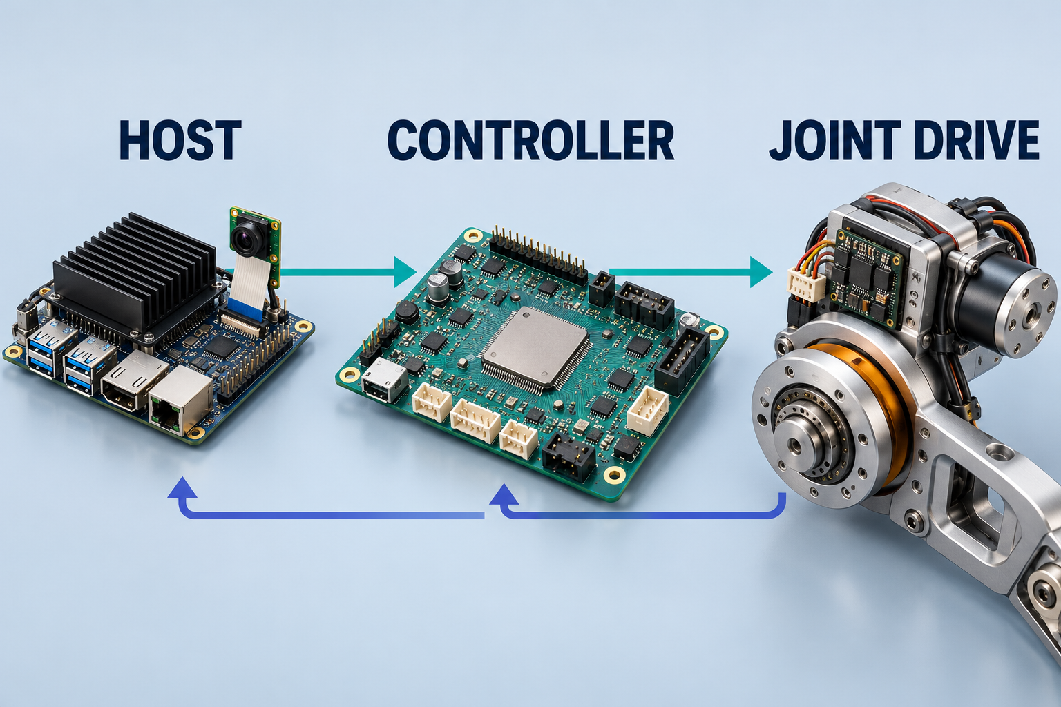
ROS 2 is middleware; an RTOS is an operating-system kernel or platform. They have different responsibilities and often work together. Selected loops can also run on a suitable Linux/PREEMPT_RT host; ROS 2’s real-time design discussion explains the application-level constraints.
Linux is useful on the host because it supplies processes, camera/network drivers, robotics libraries, and deployment tools. PREEMPT_RT improves kernel responsiveness while retaining that platform. A ROS 2 callback still needs a suitable executor/thread policy, bounded work, and prepared memory; an RT kernel does not automatically make every callback real-time. FreeRTOS offers a smaller execution environment for local firmware, rather than a drop-in home for the host’s whole Linux software stack.
Choose the timing requirement before the kernel. A vision or mapping host may need throughput and a broad driver stack while a separate MCU closes the fast loop. A Linux host that directly owns a strict control deadline needs an appropriate real-time configuration and end-to-end validation. A PC can run PREEMPT_RT; ordinary desktop workloads often do not need its tighter latency objective.
| Cost or obligation | Why it arises | Application decision |
|---|---|---|
| Possible throughput cost | IRQ-thread dispatch and PI-lock bookkeeping add work. | Measure the real workload; there is no universal overhead percentage. |
| More configuration | Task/IRQ priorities, affinity, and shared resources interact. | Validate control alongside networking, storage, and housekeeping. |
| Starvation risk | A continuously runnable RT thread can deprive lower-priority work. | Bound execution and blocking. This risk also exists without PREEMPT_RT. |
| Energy trade-offs | Some latency tuning restricts deep idle or frequency changes. | Balance power and thermals; enabling PREEMPT_RT alone does not mandate this tuning. |
| Driver assumptions | Normal spinlocks and interrupt execution contexts change. | Review custom drivers that assume a spinlock always disables preemption. |
These costs are workload-dependent. IRQ threads and priority-inheritance locking add bookkeeping; CPU placement and driver assumptions need review. Disabling deep sleep or frequency changes can trade energy efficiency for response time, but that is a tuning choice rather than an automatic effect of PREEMPT_RT. Canonical’s latency guide describes those practical trade-offs. A CPU-hogging real-time thread can starve other work even on a non-RT kernel.
This coexistence also appears in developer surveys. The two categories below cover different hardware roles; neither is a benchmark or a recommendation for a particular MCU.
- Linux/Raspbian45%
- FreeRTOS32%
- Bare-metal21%
- Zephyr RTOS17%
- ThreadX17%
- ROS 27%
- Contiki / Contiki-NG5%
- Huawei LiteOS5%
- Linux/Raspbian62%
- Android23%
- Windows19%
- Bare-metal12%
- ThreadX10%
- Zephyr9%
Read “constrained” relative to an application’s RAM, flash, CPU, power, and I/O budget. An ESP32-class controller and a Linux edge computer can face different constraints. A survey’s broad Linux result does not establish that desktop Linux fits an ESP32. Memory capacity, MMU support, drivers, and measured loop timing must be checked for the actual board.
- IMUMeasure motion
- EstimatorEstimate attitude
- ControllerCompute correction
- ESCDrive motor phases
- MotorsChange thrust
The same pattern supports drone stabilization. On supported flight boards, PX4 commonly uses NuttX; ArduPilot uses ChibiOS on many STM32 targets. Follow the PX4 flight-stack overview , system architecture , and ArduPilot porting guide .
Back to the quadruped
We can now follow the uneven-step correction all the way to the joint. The kernel organizes execution; the complete sensing, control, and actuation path determines whether it arrives in time.
For your next controller, trace one sensor event to the physical output. Name the deadline, account for each wait, and verify that boundary on hardware.
To take that controller into an application, explore VoicePing’s robotics engineering approach and define the hardware, control interfaces, and acceptance criteria together.