In this article
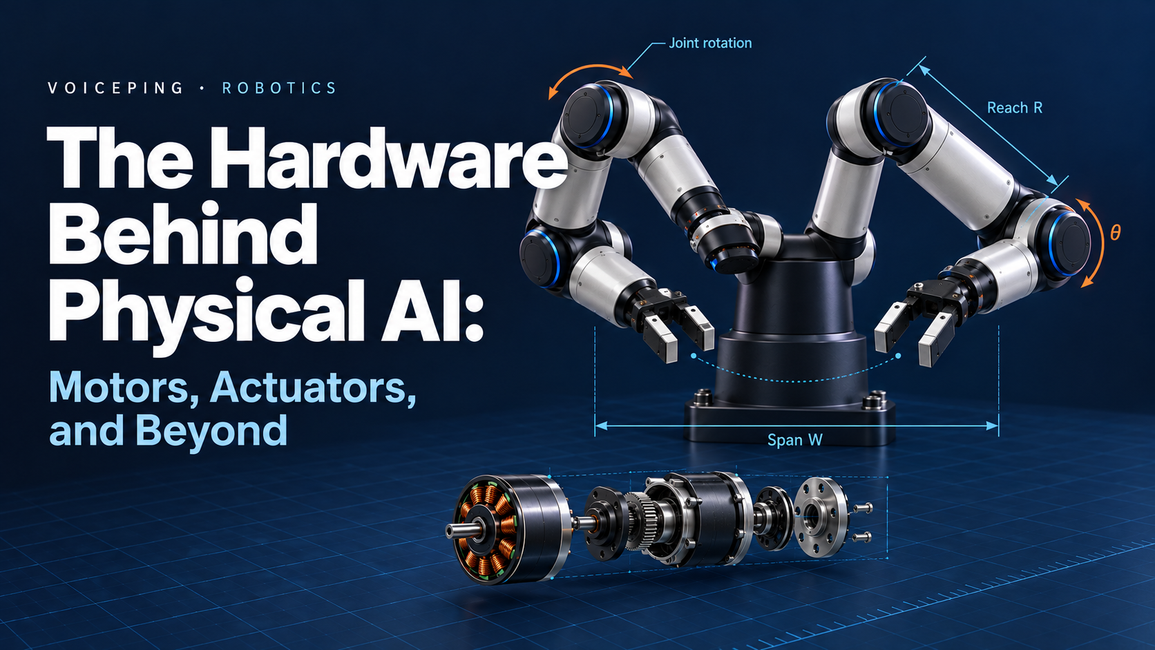
Physical AI hardware connects perception to action: reaching, carrying, making contact and recovering. Our FORTE arm work connects these choices throughout the article.
Product references were checked October 16, 2026. Illustrations are conceptual; actual operating limits come from the selected manufacturer.
1. Mechanical foundations
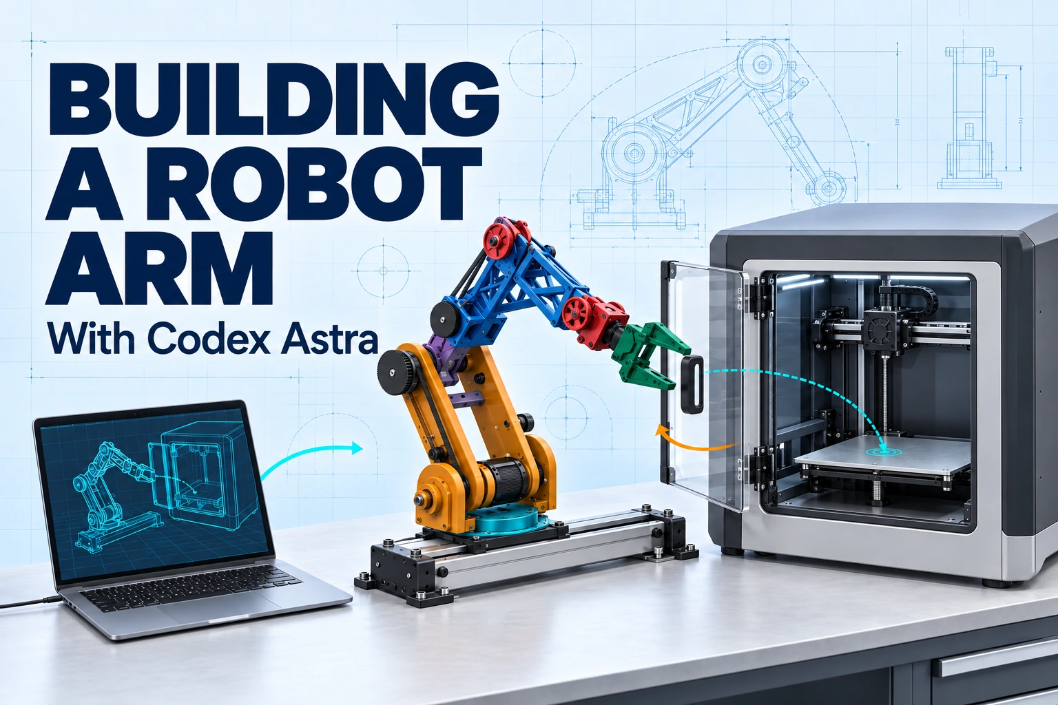
We chose FORTE’s open design , adapting geometry to our actual motors, mounts and pulleys. Printer-access simulation connected tool approach, clearance and structural fit.
Robot forms, workspace and degrees of freedom
Reaching a part is only part of the task. The tool also needs to face the right way; together, its position and orientation form a pose.
A tool pose combines two things
Position
Three position axes: x, y and z.
Orientation
Rotation about three axes sets its facing direction.
Degrees of freedom (DOF) count the arm’s independent joint motions.

What changes between five, six and seven axes

SO-101
Learning / research arm
Some pose choices are coupled: five axes cannot independently control every full pose. This can suit a task that tolerates restricted tool orientation.

UR5e
Universal Robots · industrial cobot
Six axes allow independent position and orientation control locally, within joint/workspace limits and away from singularities.

Franka Research 3
Franka Robotics · research arm
A seventh axis adds a posture choice: the elbow can move while the tool holds its pose, helping the arm clear obstacles.
Images: LeRobot · Universal Robots · Franka Robotics (two FR3 arms shown; 7 DOF each).
Gripper opening is separate tool motion. More arm axes do not automatically mean more reach.
The task still defines the workspace
Arm axes explain pose freedom. Reach, complete tool/part mass, approach angle, cycle time and clearance determine how that freedom serves the task—and the loads that reach each joint.
From geometry to joint loads
Geometry, carried mass and motion determine joint torque and speed.
Structure, load paths and end effectors
Reach only matters if the arm can support the tool and part. Their load travels through the gripper, wrist and links to the base.

- 1PartWeight + process forces
- 2GripperContact + retention
- 3WristBearings + mounting
- 4Arm linksStiffness + alignment
- 5BaseFasteners + foundation
The load begins at the contact
The tool is the first link in that path. Jaws, suction and adaptive fingers hold the part differently, so each passes the load into the wrist through a different contact.
Parallel jaws
With parallel jaws, contact geometry, pad friction and acceleration determine retention. Grip-force ratings may describe one finger or both, so identical numbers can imply different holding forces.
Suction
Suction holds through a sealed contact. Surface seal, effective area, leakage and vacuum supply set the holding force; losing the seal or supply can release the part.
Adaptive or dedicated tool
Adaptive or dedicated fingers shape the contact around the part. Compliance, damage risk, tool mass and release clearance determine how well that contact fits the task.
From the gripper into the wrist
The gripper passes those loads into the wrist, where bearings, seats, mounts and fasteners share radial, axial and overturning loads. Motor shaft bearings have separate limits from this output support.
THK cross-roller rings illustrate combined-load support. The harness moves with the joint, so cable routing also depends on bend radius, strain relief and pinch clearance throughout travel.
Through the links to the base
Beyond the wrist, the links carry those loads upstream. Section depth, ribs, unsupported spans and bearing separation set stiffness; material and fabrication determine how the structure holds its geometry under load.
| Process | What shapes the result |
|---|---|
| Printed polymer | Layer direction, creep, insert pull-out, preload and bearing-seat fit. |
| Machined aluminum | Thickness, datums, mating tolerances, tool access and shaft alignment. |
From geometry to reproducible parts
- 1
Editable CAD
Editable CAD keeps joint axes, parametric geometry and critical fits in one design source.
- 2
Fabrication files
That geometry travels as STEP for solid exchange, meshes for printing and drawings for mating and bearing-seat tolerances.
- 3
Print setup and fit
We prepared our FORTE parts in Bambu Studio. PrusaSlicer is another option. Orientation, supports, material profiles, fit coupons and post-processing affect fit.
Bambu Studio and 3MF projects
3MF is a file format for meshes, units and metadata. Bambu Lab’s Bambu Studio saves projects with models, plate layout and printer, filament and process settings. This preserves print preparation; editable CAD remains the design source. Slicer-specific settings may not transfer between applications or versions.
The tool, part, camera, mounts and moving harness shift centers of mass and change joint torque, inertia and deflection. Mass and stiffness connect the structure to the actuation requirements that follow.
Build examples: SO-101 printed parts and assembly · ALOHA 2 gripper and camera packaging.
2. Actuation and motion
Reach and carried mass shaped joint demand. Our FORTE stepper baseline and wrist pulley/cable checks connect the motor and transmission comparisons below.
Joint requirements and complete actuators
Those structural loads arrive at each joint as a demand for torque, speed and stiffness. Repeating the task adds another condition: how long that output can be sustained.
The task becomes a joint requirement
Mass farther from the joint
Output torqueThe tool, part and links load the joint through gravity, acceleration, friction and contact. Greater reach increases the lever arm.
Movement into the required pose
Speed and stiffnessTrajectory speed sets how quickly the joint moves; stiffness and bearing motion affect the tool’s deflection as it settles.
The same cycle, repeated
Duty and thermal limitsA brief torque peak and sustained operation ask different things of the same joint. Cooling and recovery determine how often that peak can return.
One joint specification connects them: torque–speed points, continuous/peak duration, allowable deflection, bearing loads and cooling describe the same task at the joint output.
Inside a complete actuator
Those requirements belong to the whole actuator: motor, transmission, support, feedback and drive. Closed-loop control adjusts commands from measurements; the ratings apply to the assembled unit.

Continuous versus peak operation
The same operating limits apply whether that joint arrives as a matched module or is assembled from separate components.
Integrated joint / smart servo
Fewer interfacesMatched motor, gearing, feedback and electronics.
Still matters: duty, bearing moments, protocol, control modes and repair access.
Motor + reducer + drive
More packaging flexibilityParts matched to load, packaging and service.
Still matters: alignment, couplings, bearings, encoder location, tuning and thermal paths.
References: Oriental Motor sizing · maxon motor data. Gravity-loaded axes may need a separately engineered holding brake.
From joint demand to motor choice
The motor supplies motion inside the actuator, while the transmission changes its output. Their combined behavior meets the same joint demand.
Motor technologies

The same joint demand can be approached with different motor families. Motor, drive and feedback together determine the available performance.
| Decision | Brushed DC ↗ | Hybrid stepper ↗ | BLDC / PMSM ↗ |
|---|---|---|---|
| Strong fit | Wheels, pumps, economical geared motion. | Indexed/Cartesian motion; moderate-speed arms. | Dynamic joints, continuous rotation, torque control. |
| Torque and speed | Torque falls with speed at fixed voltage; gearing sets output. | Strong low-speed torque; inductance/back-EMF limit high-speed current. Measured curves show the usable range. | Current sets torque until bus-voltage limits reduce phase current. |
| Efficiency and heat | Brush/contact/friction and winding losses; stall heats without motion. | Regulated phase current can stay high at light load. Reduced holding current helps. | Copper, iron and inverter losses remain; holding torque needs current. |
| Precision | Feedback required; backlash and load deflection remain. | Microsteps improve smoothness/resolution, not equivalent loaded accuracy. | Encoder, tuning, cogging, reducer and stiffness set accuracy. |
| Feedback | Encoder + controller → position/velocity servo. | Open loop cannot confirm position or every lost step; closed loop adds feedback and recovery limits. | Rotor position supports commutation/torque control; sensorless limits matter near zero speed. |
| Cost and complexity | H-bridge; servo operation adds sensing, tuning and maintenance. | Accessible ecosystem; resonance, current settings and acceleration shape performance. | Three-phase inverter, current sensing and commutation; integrated joints package this work. |
Where the energy goes
The heat differences above come from how each motor and its drive turn electrical input into motion. Peak datasheet efficiency describes one operating point, while the robot’s task moves between acceleration, travel, braking and holding.
Electrical power, including the drive.
↘ Heat + other losses
Mechanical power at the shaft.
- Acceleration
- Motion
- Braking
- Hold / idle
Zero speed, zero shaft power. Holding a load can still draw electrical power.
Braking changes the balance. Regenerative braking changes the direction of energy flow.
Motor fit depends on that cycle
- A simple fit when
- Torque and speed fit the measured curve and thermal limits.
- Key limit
- Closed-loop feedback shows position. It cannot remove winding losses or create extra torque.
- Worth the integration for
- Speed, sustained duty, torque control or low-reduction contact behavior.
- Key limit
- Continuous torque depends on actual cooling. A brief peak is not a sustained rating.
- A fit when
- Simplicity, size and cost outweigh brush maintenance and electrical noise.
- Key limit
- A geared brushed servo is an option; positioning accuracy still depends on the complete joint.
Motor families in real robots
- StepperOriental Motor OVR ↗
4-, 5- and 6-axis arms. αSTEP AZ motors with battery-free absolute feedback.
- StepperST Robotics R17 ↗
Microstepped hybrid motors + encoder watchdogs. Standard R17; high-speed variants differ.
- BrushlessUnitree G1 ↗
Manufacturer-specified internal-rotor permanent-magnet synchronous motors. A humanoid has different motion and integration needs from a benchtop arm.
Architecture examples, not a like-for-like comparison of speed or duty.
References: maxon motor data · Adaptive microstepping · ODrive control. Efficiency and accuracy depend on the motor/drive system and its operating conditions.
Into the transmission: torque–speed curve, current limits, rotor inertia and feedback requirements.
Transmissions and drive architecture
The motor’s torque still has to reach the wrist. Moving the wrist-drive motor farther up the arm changes what the links carry—and introduces a transmission between that motor and the same wrist joint.
The wrist carries its motor
The drive sits at the wrist, so upstream joints carry and accelerate its mass along with the tool.
The same wrist, driven from upstream
The wrist motor sits farther up the arm. A cable or belt carries its motion through pulleys; routing and compliance become part of that drive.
Only the wrist drive changes position. The same wrist joint is ringed in purple; the other joint motors stay gray. Moving mass away from the wrist reduces its contribution to upstream inertia, while the remote transmission adds routing and compliance. Clearance, stiffness and service access still belong to one mechanical path.
Placement leads to the next question: reduction
Wherever the motor sits, the joint may need a different torque and speed from the motor shaft. Reduction changes that relationship, as well as how much motor inertia is felt at the output.
Direct drive
No reducerMotor torque and speed reach the joint directly, before losses.
Low reduction / QDD
Lower inertia amplificationBacklash, feedback and safe system behavior still matter.
Higher reduction
A faster motor can drive a slower jointReflected motor inertia and transmission effects increase in importance.
Gear clearance, elastic stiffness, bearing loads and service access.
Motor relocation, routing, tension, stretch and slip.

Mechanism trade-offs
Load, lost motion, stiffness, efficiency and life determine which transmission fits.
| Drive | Typical fit | What decides the fit |
|---|---|---|
| Planetary ↗ | General-purpose joints, wheels, sourced reduction. | Backlash grade, stages, bearing capacity, life. |
| Strain-wave ↗ | Compact, high-ratio positioning. | Compliance, friction, flexspline fatigue, duty. Low backlash ≠ infinite stiffness. |
| Cycloidal ↗ | Loaded industrial joints, shock loads. | Bearings, eccentric alignment, accuracy, mass. Printed parts lack industrial durability evidence. |
| Timing belt ↗ | Remote motors, linear axes. | Tension, engagement, pulley size, stiffness, clearance. |
| Capstan / cable | Light distal mechanisms, contact-sensitive arms. | Pretension, stretch, slip, terminations, travel. |
| Direct drive / QDD | Dynamic, backdrivable joints. | Motor torque/current/thermal budget and sensing. QDD has low reduction; direct drive has none. |
Mass feeds back: wrist-mounted reducers add upstream torque demand; remote actuation adds routing and compliance.
References: APEX · Harmonic Drive · Nabtesco · FORTE belt/capstan · Berkeley printed reducers.
The complete joint matters
Links, mounts and tooling form the load path. Feedback reveals the resulting motion.
Schematic geometry; QDD has no universal ratio cutoff. Motor mass farther from an upstream joint adds more rotational inertia, alongside the carried load.
3. The robot in operation
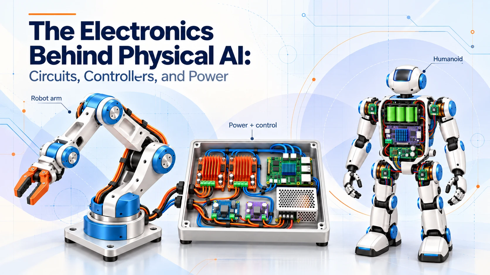
Our host → Pico 2 → driver path is planned; powered testing remains ahead. Simulation improved reach with a moving base but lengthened the cycle. Physical accuracy and reliability remain unmeasured. Our electronics story follows the circuits, controllers, wiring and power decisions.
Feedback and perception
The mechanism moves the tool; feedback tells us how it moved. Perception then relates that motion to the part, the fixture and the contact between them.

Knowing where the arm is
As the tool approaches the fixture, encoders report joint motion. Motor angle and reduction estimate output angle in a rigid transmission; an output encoder observes it directly. Neither measures link bending.
Temperature sensing and travel references describe the operating limits around that motion. They answer a different question from the camera: what is happening inside the robot?
Locating the part and fixture
RGB (color) images reveal appearance and features; depth adds scene geometry. Pixels alone are not metric coordinates, and material, lighting and occlusion can limit valid depth returns. Camera position changes which view is available.
Fixed camera
Stable overviewOcclusion and registration to the base determine its coverage.
Wrist camera
Close detailMoving cables, hand–eye calibration and changing viewpoints come with that closer view.
Camera intrinsics describe lens/image geometry. Hand–eye/base transforms relate the camera to the arm; synchronized timestamps relate their measurements in time.
A fiducial marker is a known black-and-white pattern fixed to the scene. Its measured size gives a calibrated camera a reference for estimating the fixture’s position and orientation.
How ArUco patterns identify a reference
In OpenCV ArUco, DICT_4X4_50 names a pattern family and ID 7 selects one pattern. These are identifiers, not coordinates. Known marker size, a white margin, unscaled printing, calibration, lighting and visibility affect the estimate.
Understanding contact as the tool arrives
The fixture’s pose describes where contact should happen. Direct force/torque sensors measure local loads; motor-current estimates include model uncertainty. Tactile sensors add local contact or pressure patterns. Force, vision or another independent observation can then establish whether the part actually seated.
VoicePing’s robot-control prototype connects camera input and written instructions to pick-and-place. The same page documents webcam/LiDAR experiments alongside that application context.
The hardware behind those observations
| Observation | Example / primary link | Integration decision |
|---|---|---|
| Joint angle | AS5048A · magnetic/SPI | Magnet alignment, accuracy; motor versus output placement. |
| Wrist force / torque | ATI Mini45 Titanium | Range, overload, interface and tool/gravity compensation. |
| Phase-current measurement | TI INA240 · amplifier | Shunt + ADC + motor model; not direct contact force. |
| Temperature | TI TMP117 · I²C | Thermal attachment; board readings may lag windings. |
| Travel reference | Omron D2F | Rating, force, overtravel, input conditioning; ordinary switches are not safety-rated systems. |
| RGB scene image | Pi Camera Module 3 | Lens, focus, exposure, mounts and host interface. |
| Close-range scene depth | RealSense D405 | Range, field of view, material, USB bandwidth, mounts. |
| Local contact shape | GelSight Mini | Contact patch, mounts, elastomer wear, processing; complements scene vision. |
Observation → pose estimate → motion → outcome evidence.
Bandwidth and calibration matter alongside resolution. A marker pose is a reference; current is not contact-force ground truth.
Power, drives and compute
The sensors and joints now meet in one electrical system. Power reaches the motor through a drive; commands and feedback connect that drive to a controller and host.

Power reaches the motor through its drive
| Motor / actuator | Drive example | Important boundary |
|---|---|---|
| Brushed DC | H-bridge + current sensing; TI DRV8876. | Bus/stall current, heat and protection; encoder feedback for positioning. |
| Two-phase stepper | Current-regulating drive; Pololu DRV8825. | Phase-current limit, compatible bus voltage, cooling and transients. |
| BLDC / PMSM | Feedback-compatible inverter; ODrive S1. | Bus/current limits, motor parameters and a regeneration sink. |
| Integrated bus servo | Internal drive + vendor bus. | Voltage, pinout, protocol and simultaneous demand vary by actuator. |
The drive’s bus voltage and full-cycle demand determine the supply. Mean Well LRS-350-24 is a 24 V · 14.6 A · 350.4 W nominal example; acceleration, auxiliaries, inrush, temperature derating and overload behavior determine its fit. Motor phase currents do not sum directly into supply current.
Braking can return energy to the bus, while supplies normally do not absorb it. S1 documents one brake resistor per drive, within resistance, pulse-energy, duty and cooling limits.
Commands pass through three different roles
The host interprets the task
Pi 5 runs Linux, cameras, planning and logs. A GPU host suits heavier policies when measured latency, memory, power and cooling justify it.
The controller handles local timing
Pico 2 and ESP32 run firmware for timed I/O, encoders, step/dir or bus bridging. GPIO carries logic, not winding power.
The drive produces motor output
Current regulation stays near the motor. Feedback, tuning, limits and stop behavior depend on the selected drive and control mode.
Those roles meet through rated wiring, connectors, branch protection, DC conversion and strain relief. Pi 5 needs regulated 5 V; mains assemblies involve enclosure, protective earthing and qualified work. Gravity loads also need retention during stops.
ROS 2 carries messages; ros2_control connects joint state and commands to drivers. URDF/Xacro describes geometry, axes and limits; MoveIt 2 turns the model and scene into trajectories. Real-time behavior still depends on the hardware and interfaces.
More on electronics and software interfaces
Classic ESP32 TWAI needs an external CAN transceiver; chip variant, 3.3 V logic and isolation matter. Pi’s 27 W USB-C supply is a power reference. The electronics story follows the circuits and wiring in more depth.
Further tools: Gazebo / MuJoCo for simulation; OpenCV / LeRobot for vision and policies; KiCad for schematics; RoboDK for offline programming. Model, timing, feedback, fault handling, OS/driver support and licenses define the usable stack; development docs may include unreleased interfaces.
For conveyors and existing machines, VoicePing’s application review connects hardware, vision and control to the same workflow.
Into validation: these power and signal paths define the system whose task performance, operating limits and fault responses can be measured.
Assembly, calibration and validation

Motion, sensing and power return us to the task: a correctly placed part, within the required cycle time and operating limits.
Integrated evidence is still ahead for our arm. Bench behavior—polarity, feedback, current limits, support and stopping—and calibrated joint, tool and camera references would establish the basis for loaded task measurements.
From motion to a measured result
Accuracy
Distance from intended pose.
Repeatability
Spread of repeated returns under matched conditions.
Accuracy and repeatability depend on workspace and load. Independent seating, release and recovery evidence connects those motion measurements to the workflow.
| What the task reveals | Evidence behind the result |
|---|---|
| Task performance | Placement, full-cycle timing, seating and release. Agreed limits, failures and interventions make success rates meaningful. |
| Repeated operation | Representative load/duty reveals temperature, drift, wear and retention against component limits. |
| Interrupted operation | Controlled command loss, stale vision and jams reveal stopping, gravity retention and recovery. |
| Another build or repair | Controlled parts and assembly/calibration revisions, repeated end-of-line tests, replacement, recalibration and service time. |
Verification means meeting requirements; validation means solving the workflow. A VoicePing robotics proof of concept connects the task to agreed success, cycle-time and intervention criteria.
Evidence that follows the robot
rosbag2 records timestamped commands, states and sensor messages. Outcome measurements, limits, pass/fail video and hardware, firmware, software and calibration versions make results traceable.
Production readiness adds hazard analysis, protective functions, reliability and repeatable manufacture/service, supported by wiring, fabrication, inspection, spares and supplier records. Demonstrations establish feasibility; sustained evidence supports release.
Back to the original task
Picking → orientation → seating → independent placement evidence.
The hardware story comes together in a measured task outcome.