In this article
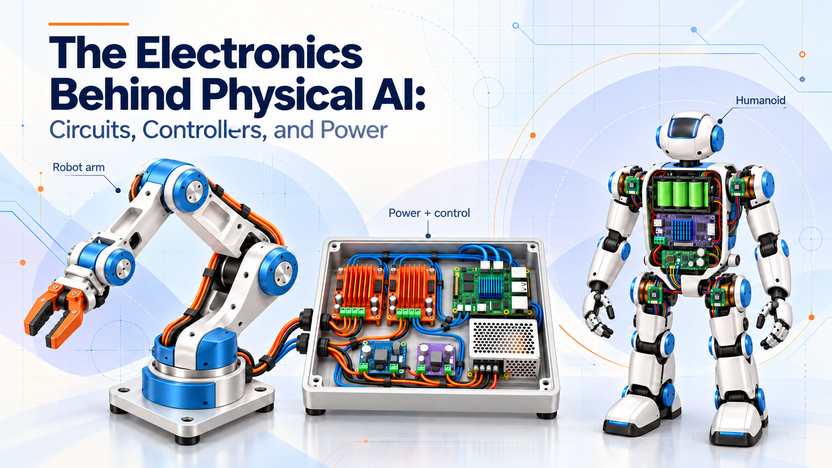
Our robot-arm electronics work at VoicePing began with a Pico 2, separate motor drivers, and a power-supply plan. We followed the signal and power paths to understand how the boards fit together.
Circuits and electronic components
Our arm first needed a clear separation between a movement instruction and the energy to carry it out. That distinction stayed with us as the actuators changed.
Why our first circuit kept control and power separate
Our original FORTE plan paired Pico 2 with separate stepper drivers. The controller requested movement; the drivers supplied motor current.
A host handled the application while Pico handled motion signals. We kept the signal path and the motor-power circuit distinct.
Our original stepper path used separate motor power and driver signals.
The circuit became motion.
Our separate ESP32 bench test made the chain visible: a command became motor-and-pulley motion.
The portable arm used STS3215 smart servos; our later BLDC experiment separated motor, encoder, and drive again. These were different builds, not one combined parts list.
What sat around the controller
The small parts gave each circuit a job: switching current, stabilizing power, adapting signals, protecting loads, converting voltage, and making connections serviceable.

Our parts list included capacitors, resistors, transistors, a suppression diode, and a logic buffer. The roles are easier to see together than as a shopping list.

The brushless joint added rotor feedback and current control to that same picture. FOC regulates current relative to rotor position.

Our prototype choice
MKS XDrive MINI
Our later prototype paired the Makerbase drive with an LA8308 KV90 motor.

A researched comparison
moteus r4.11
We compared its integrated FOC, encoder, and CAN-FD control with our own module choices.
When feedback changed the story
Our portable-arm notes reported an overload response that removed gripper torque. The object dropped. That made feedback and fault behavior part of the same problem.

The driver’s current regulation did not tell us the achieved joint angle. Our command and the robot’s measured state were different information.
Once we understood the circuit’s responsibilities, the next decision was which board would do each job—and how its information would reach the joints.
02Controllers and wiring
Our arm’s board choices became clearer when we separated host computing, embedded motion, and the motor drive’s local control.
Why Pico anchored our original plan

We placed motion firmware and driver signals here. Motor power stayed with the drivers.
Board documentation ↗Pico 2 anchored our original motion-controller plan. We explored ESP32-S3 for control and camera work, and used Raspberry Pi to explain the host-computer role.
Our decision lens: timing, interfaces, compute, power, and cooling.
We did not need all three boards in one arm. The workload determined the combination.
How a command reached a joint
We separated perception, communication, and joint control. Each needed the right information at the right time.
Why we built a small HTML motor bench.
Our local HTML interface brought step presets, direction, connection status, and activity into one place. That made repeated bench checks easier to compare.
What each connection carried
Commands + telemetry
Motion requests
Addressed control + feedback
Distributed communication
SPI and I²C covered nearby peripherals. A limb bus needed its matching interface and wiring; with a suitable moteus drive, a separate Pico could be optional.
Host updates and fast local motor loops solved different jobs. We treated timing as a system question, not one universal “AI speed.”
From words to arm motion
Our natural-language robot-control prototype brought the wider story into view: a request still had to reach the arm as motion commands.

The harness became part of the design
Our wiring audit caught thin 30 AWG wire proposed for a general power-harness role. It pushed us to consider current, cable length, joint movement, and service access together.

Matched to load and interface.
Flexibility, bend room, strain relief.
Identifiable ends and secure connectors.
The GPIO, driver inputs, and motor rail belonged to different electrical domains. Their thresholds, current requirements, polarity, and isolation shaped the interface.
After the command path and harness, we could trace the energy path. That led from choosing a supply to understanding what the robot did with power while moving, holding, and stopping.
03Power and reliable operation
The arm’s electronics needed distinct power rails. Moving, holding a load, and stopping placed different demands on that system.
Why “a 24 V supply” was only the beginning
The original plan used LRS-150-24. A later larger-motor proposal used LRS-350-24. We compared those configurations separately.
Same voltage. Different capacity.
Bars compare published nominal output capacity.
We budgeted for moving, holding, startup demand, wiring loss, and heat. Motor phase-current settings did not add up directly to DC supply current.
Power reaches compatible drivers, then motor windings.
Separate conversion or the board’s specified input supply.
For the selected DS3225-type plan, not every servo.
Our original gripper example used a 6 V Pololu regulator. A different actuator needed its own voltage and current assessment.
Protection, cooling, and stopping belonged to that same design. The proposed relay and reset button did not by themselves establish the robot’s stopping behavior.
What stopping added to our power story
A slowing or lowering joint could return energy toward the DC bus. We had to consider where that energy could go, as well as how the supply delivered it.

ODrive documents resistor braking; moteus documents regeneration limiting and flux braking. These are alternative drive capabilities, not features established on our XDrive MINI.
Power removal changes the robot’s physical behavior, too.
Our gripper report made power removal physical: losing holding torque could release a grasp or move a loaded link.
What we can say.
What our next evidence needs to show.
We had component checks, gripper observations, and bench footage. Complete-arm behavior still needed its own measurements.
Our next evidence needed to connect the task, load, configuration, and operating time. That is where an AI command becomes useful physical work. This task-to-system connection also underlies VoicePing’s custom robotics development.
Circuit → Controller → Harness → Power → Evidence
Products we explored
Sources & development notes
How to read the examples
Our FORTE plan, portable arm, and BLDC prototype were separate development stages. Illustrations explain functions; product links identify examples. They are not exact schematics or product photographs.
The bench interface reports commanded rotation without a position sensor. Its stop-pulses action can leave holding power on. Full-arm performance, final wiring, firmware, and stopping behavior still require integrated measurements.
Our component notes include 100 µF electrolytics, 0.1 µF ceramics, 1 kΩ and 10 kΩ resistors, a 1N4007 diode, 2SC1815 transistors, and an SN74AHCT125N buffer. Relay coil voltage and permitted contact load are separate ratings. Reported sensor transients need repeated samples and message-integrity checks.
Internal sources document plans and reported observations. Manufacturer and project references support the technical explanations. Research checked 19 October 2026. Illustrations are conceptual; board photographs were supplied as references.
- Pico 2 datasheet · ESP32-S3 documentation
- Raspberry Pi computer documentation
- Makerbase MINI hardware / firmware
- moteus r4.11 specifications · Control modes
- moteus wiring and regeneration
- ODrive braking configuration
- Mean Well LRS-150 datasheet · LRS-350 datasheet
- Pololu 6 V regulator · Phase versus supply current
- ros2_control timing and execution