In this article
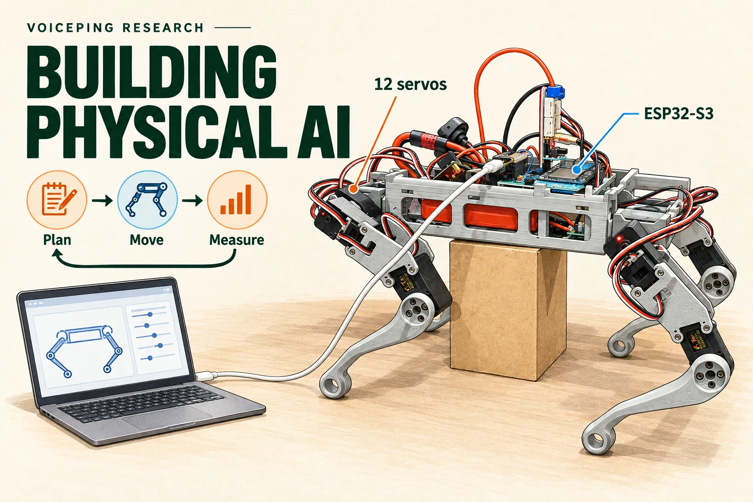
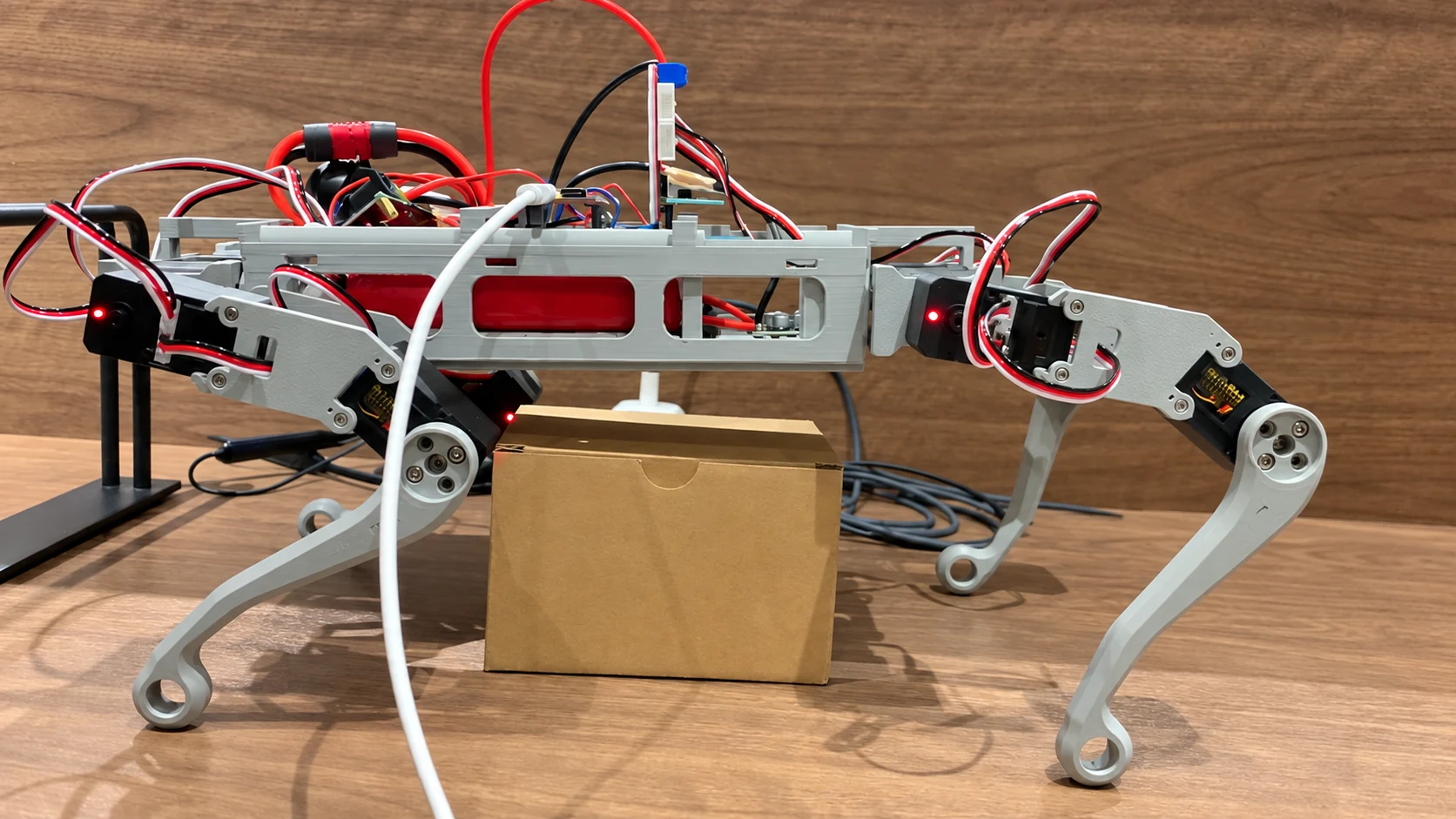
At VoicePing, we are exploring physical AI through machines we can build, measure and improve. A small quadruped was one of our first experiments. We wanted to build a machine that could sense its surroundings, move through them and give us useful measurements of what happened.
A quadruped lets us study balance, motor control and contact with the floor in one machine. Three feet can support the body while the fourth moves. A late joint, a slipping foot or a flexible mount can upset that movement. Once walking is repeatable, we can test how vision helps the robot choose where to step.
As of October 30, 2026, the robot has stood and made brief balance corrections. We have yet to complete a verified walking cycle on the robot. Its movement controller follows programmed rules. We tested AI perception models separately, with learned walking still ahead.
Our earlier article explains why we chose a robot dog for this research . Here, we look at the build itself: what changed, what we measured and what remains to be demonstrated.
A laptop, a controller and twelve motors
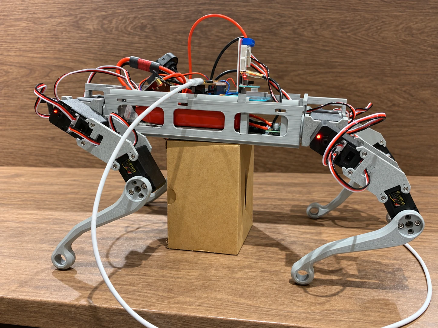
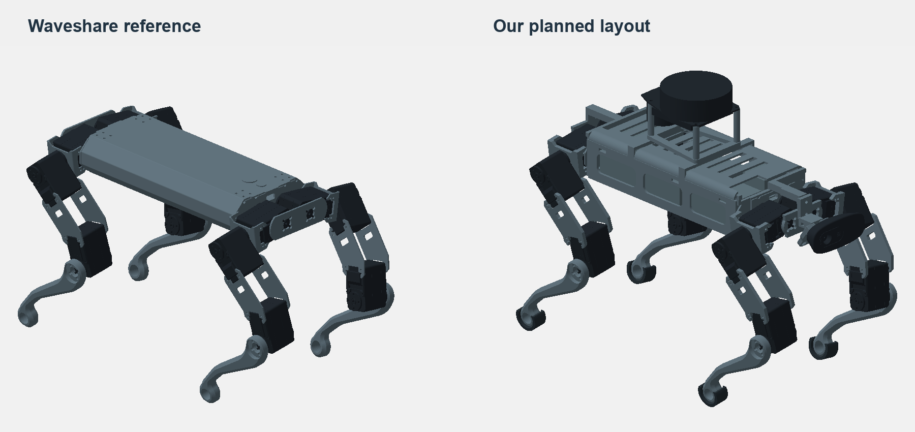
The robot uses twelve STS3215 servos, three per leg, and an ESP32-S3 control board. We adapted the printed body from Waveshare’s quadruped design . Each servo combines a motor with a position sensor and its own controller. We can ask it to move to an angle and read back its position and health data.
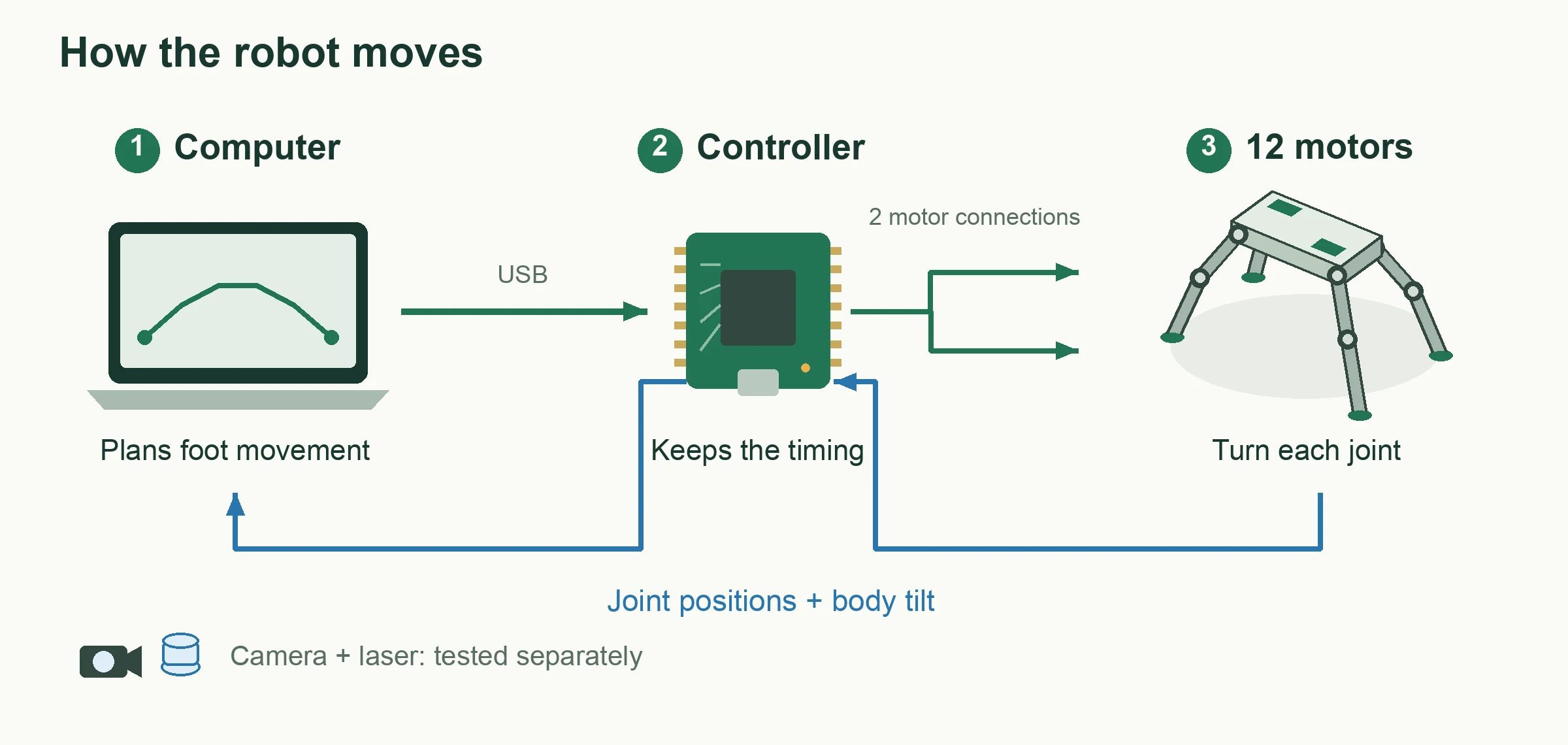
An external Mac chooses foot movements and calculates joint angles. The ESP32 sends those targets to the motors at the planned times, collects their readings and responds if commands stop arriving. Each servo handles its own movement toward the requested angle.
This split makes it easy to change the planning software on the laptop. It also creates a timing problem: upcoming commands must reach the ESP32 before the robot needs them. We send movement ahead of time so the controller can continue while the laptop calculates the next part. The setup currently depends on its USB tether.
From a foot position to a movement
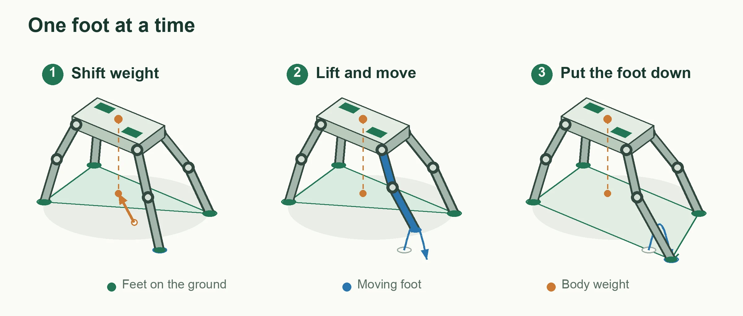
Our first walking plan uses a slow crawl. Before lifting a foot, the planner shifts the body so its estimated center of mass sits over the triangle formed by the other three feet. This is a quasi-static crawl. We chose it because we can examine each weight shift and foot placement separately. During testing, we still need to watch for slipping or feet losing contact.
We choose where the foot should land, then calculate how far each joint must turn. This is inverse kinematics, or IK. Our leg layout allows a direct geometric calculation using the link lengths and joint axes from the CAD model. We chose this analytic method to avoid repeatedly searching for an answer. The planner checks that the angles stay within the joints’ limits and place the foot at the requested point. When several poses work, it picks one close to the current pose.
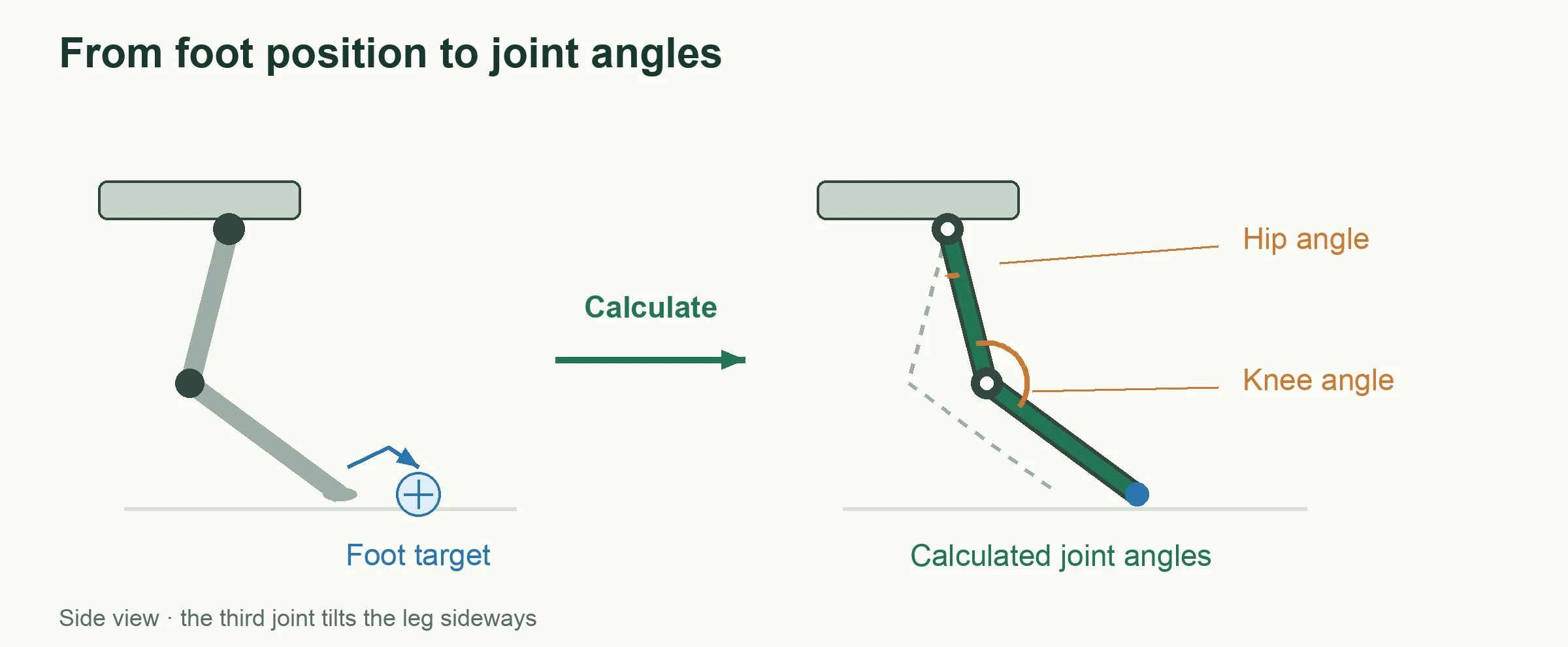
We connect those poses with smooth curves called quintics. They keep the requested position, speed and acceleration continuous between movement segments. All twelve joints use the same clock. We also limit how fast each joint moves and how sharply its acceleration changes. A demanding movement gets more time.
Getting commands to the motors on time
Planning the next step
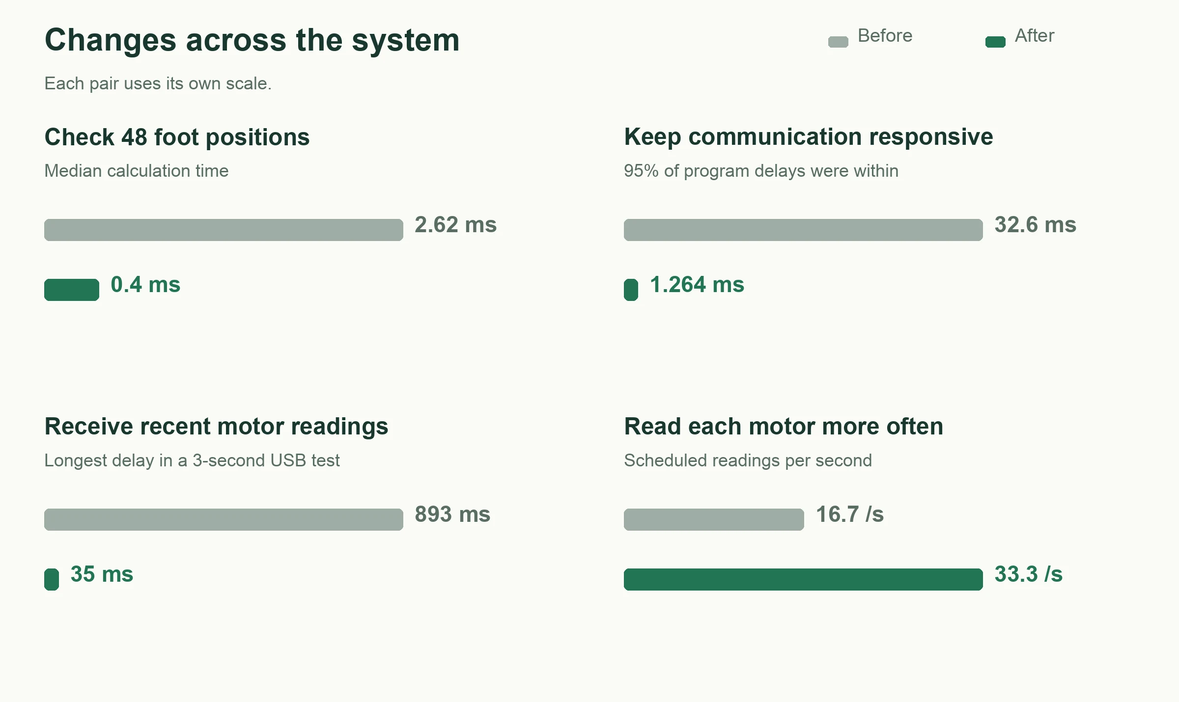
The planner kept rebuilding unchanged leg geometry and repeating checks. We saved those calculations and checked several foot positions together. Checking whether 48 positions were reachable took 0.40 ms, down from 2.62 ms, using the median of repeated runs. Tests against the original calculations covered changed geometry, joint limits and difficult targets.
The movement itself also contained unnecessary waiting. There were compulsory pauses, a shift that produced no motion, and timing rules that slowed the whole sequence when one part needed more time. We removed redundant waits, timed each phase separately and replaced a two-part foot lift with one smooth arch. In the same software test, the planned cycle shortened from 16.08 to 11.76 seconds.
Long pauses caused a separate problem. During one physical attempt, the laptop spent about 1.5 seconds repeatedly searching for a reachable foot placement before sending any walking command. We limited repeated failed searches within each planned section. We also moved planning into a separate process so it could run without holding up communication. In a laptop timing test, 95% of waits for the main program to resume were at or below 1.264 ms, down from 32.6 ms.
For the next trial, we prepared a complete four-leg cycle in advance. This reduced the planning work needed during movement. The prepared cycle monitors tilt, with active posture correction before and after the cycle.
Keeping USB up to date
The laptop read one available chunk of data per check while the board kept sending updates. Old position and tilt reports accumulated. We changed the reader to collect several chunks, briefly allowing the operating system to refill its buffer, while limiting the time spent reading. In a three-second disarmed hardware check, the largest observed delay fell from 893 to 35 ms.
We also moved bulky setup details out of frequent status messages. In a comparison using the same robot state, one message shrank from 4,647 to 3,197 bytes. The board sends complete messages, gives clock replies priority over waiting status reports and reserves time to receive commands.
We also measured how long commands took to reach the board. The laptop put a command into a USB buffer in about 0.15 ms. For a command-sized message, about 19 ms had passed by the time the board generated its response. Commands sent only 20–22 ms before their planned start could arrive too late. We needed to allow time for delivery and processing as well as calculation.
Using both motor connections
The motors use two independent 1 Mbps serial connections, with six servos on each. Each connection already used a group-write command, SYNC_WRITE, to put all six target positions in one message. We improved this by starting both transmissions together. The calculated wire time to transmit both messages fell from 1,120 to 560 μs, before scheduling and processing overhead.
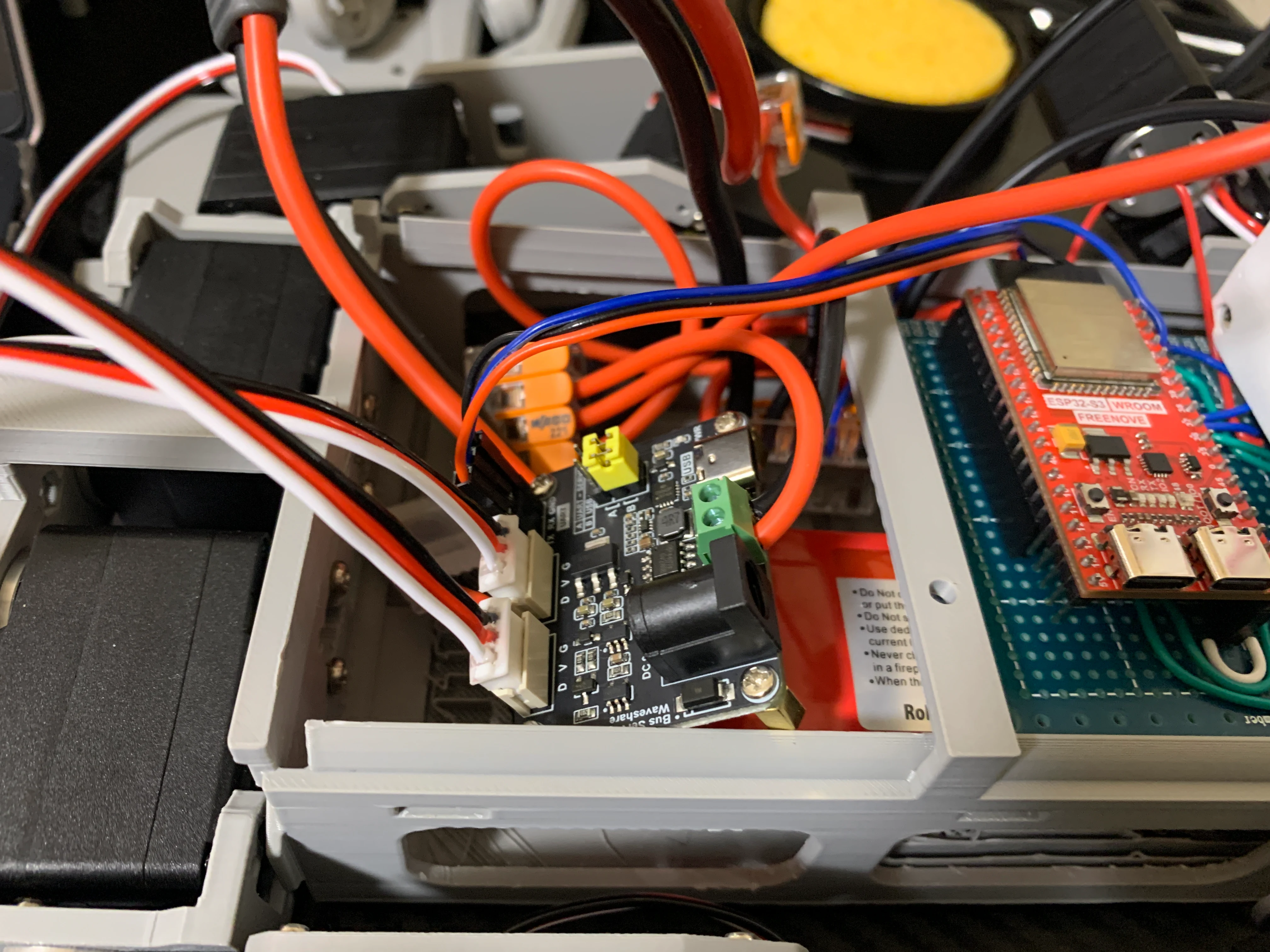
Reading positions works differently. We ask one servo at a time on each connection for its position and health data. Starting one read on each connection together lets both responses progress independently. A slow reply on one side no longer delays starting the other side’s read.
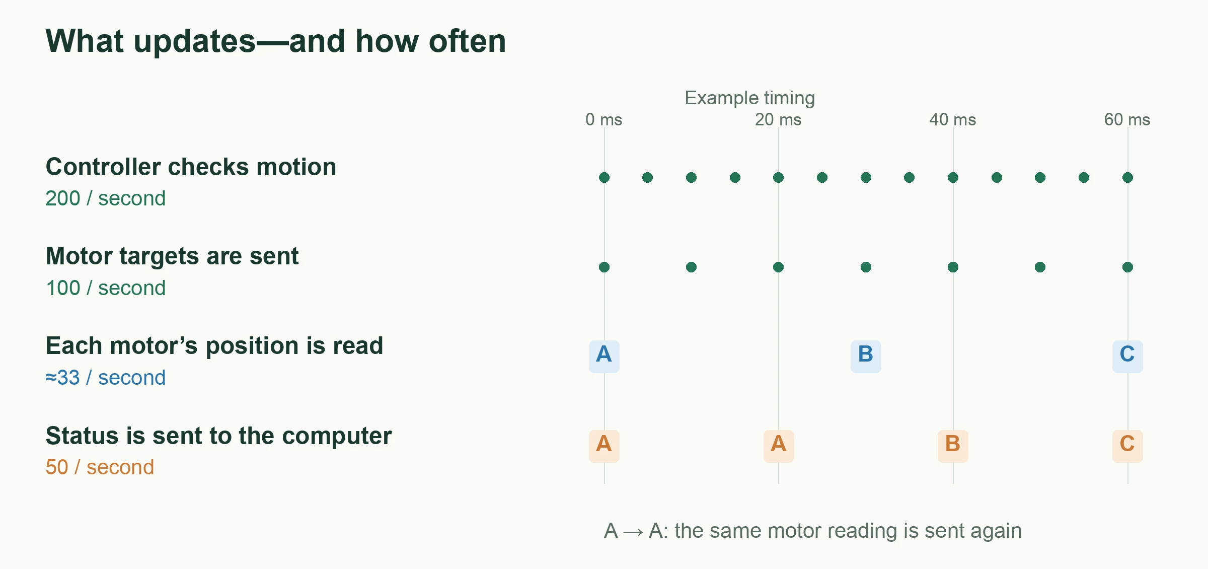
The resulting schedule provides a new reading from each motor about every 30 ms, or roughly 33 times per second. The controller sends status to the laptop 50 times per second using the latest readings it has received. This means two status messages can carry the same motor reading. Saved hardware records showed typical 30 ms intervals between motor readings, with occasional longer gaps.
Working with the hardware
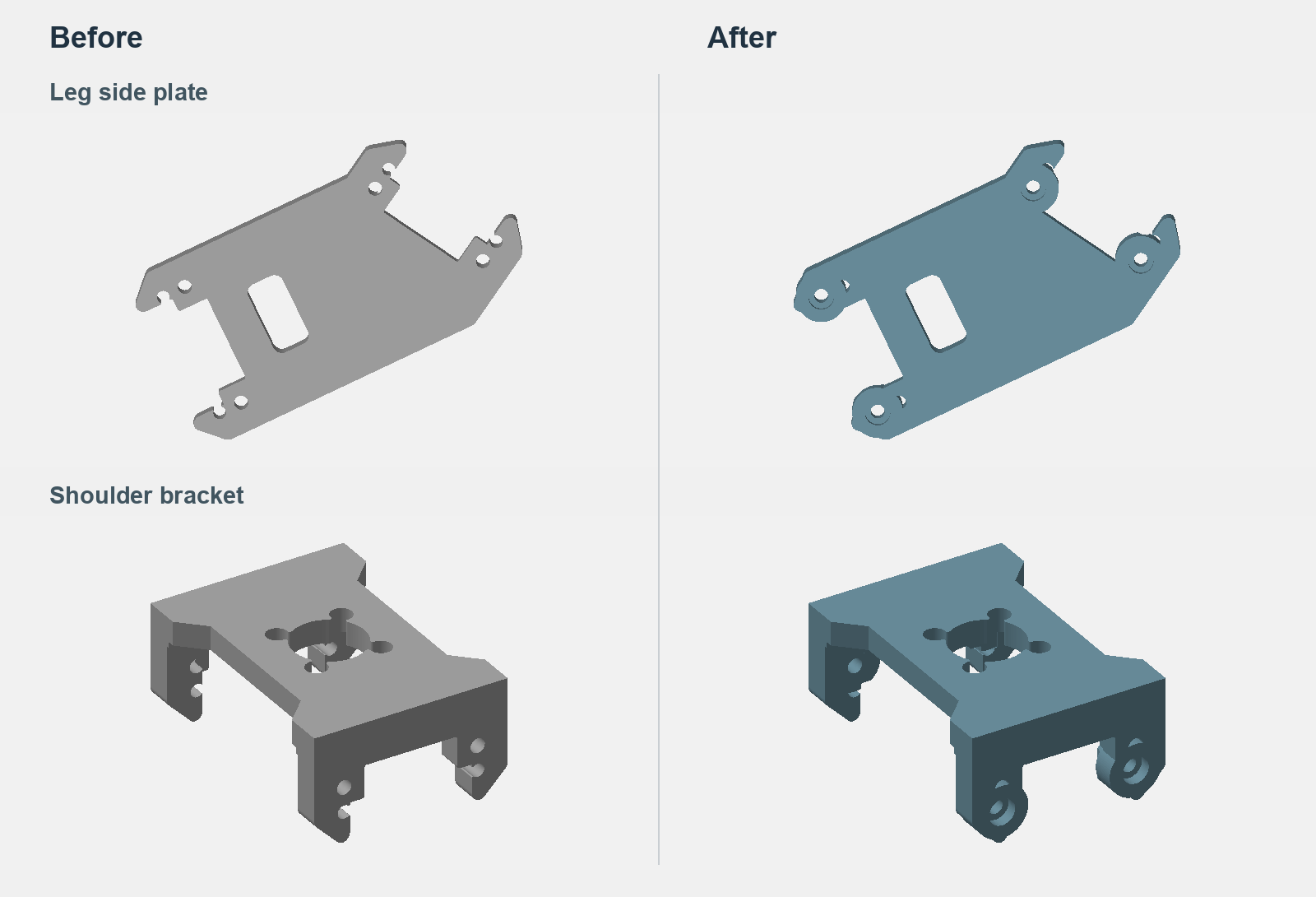
Some printed motor mounts had gaps in their screw seats that needed closing. Lower-leg connections needed recesses that gave the actual screws enough reach. A left/right export error also required a correction to the printable parts. Strength testing remained unfinished for some repairs.
Calibration connected the motor readings to the assembled joints. We checked movement directions and usable travel. Where a position count wrapped back to zero within that travel, we changed its zero point and translated the saved measurements. Five corrections were verified, and eleven existing ranges were retained. That saved repeated physical measurement.
The BNO085 tilt sensor needed communication fixes before its readings became usable. We fixed how the software assembled messages arriving in pieces, requested related measurements together and waited for the sensor to confirm those requests. After aligning it with the body, we used tilt to request small posture corrections and measured rotation to damp the response. One short test reduced sideways/forward tilt from about 1.41°/0.64° to 0.13°/0.14°. Sustained balance under disturbances remains to be tested.
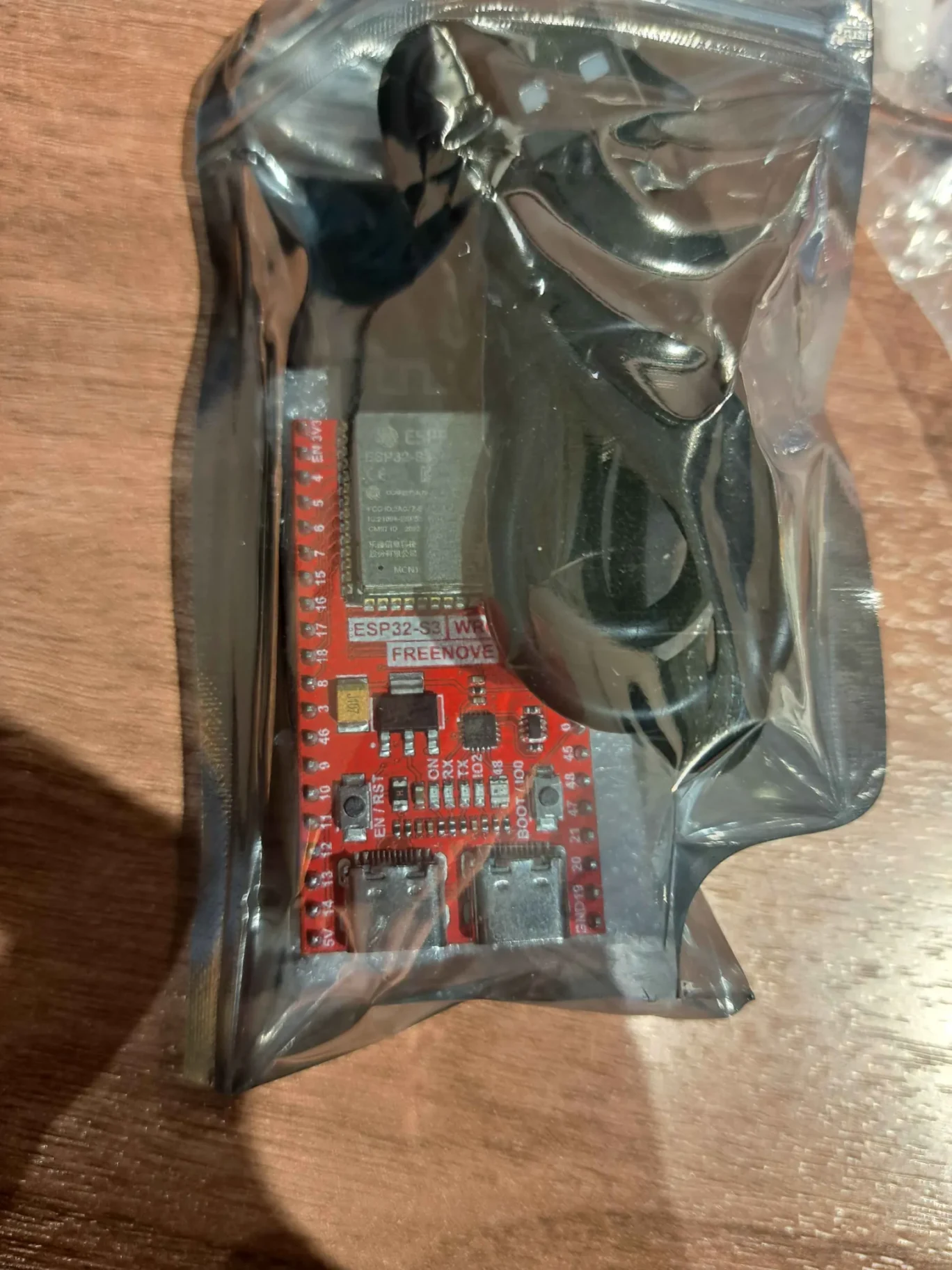
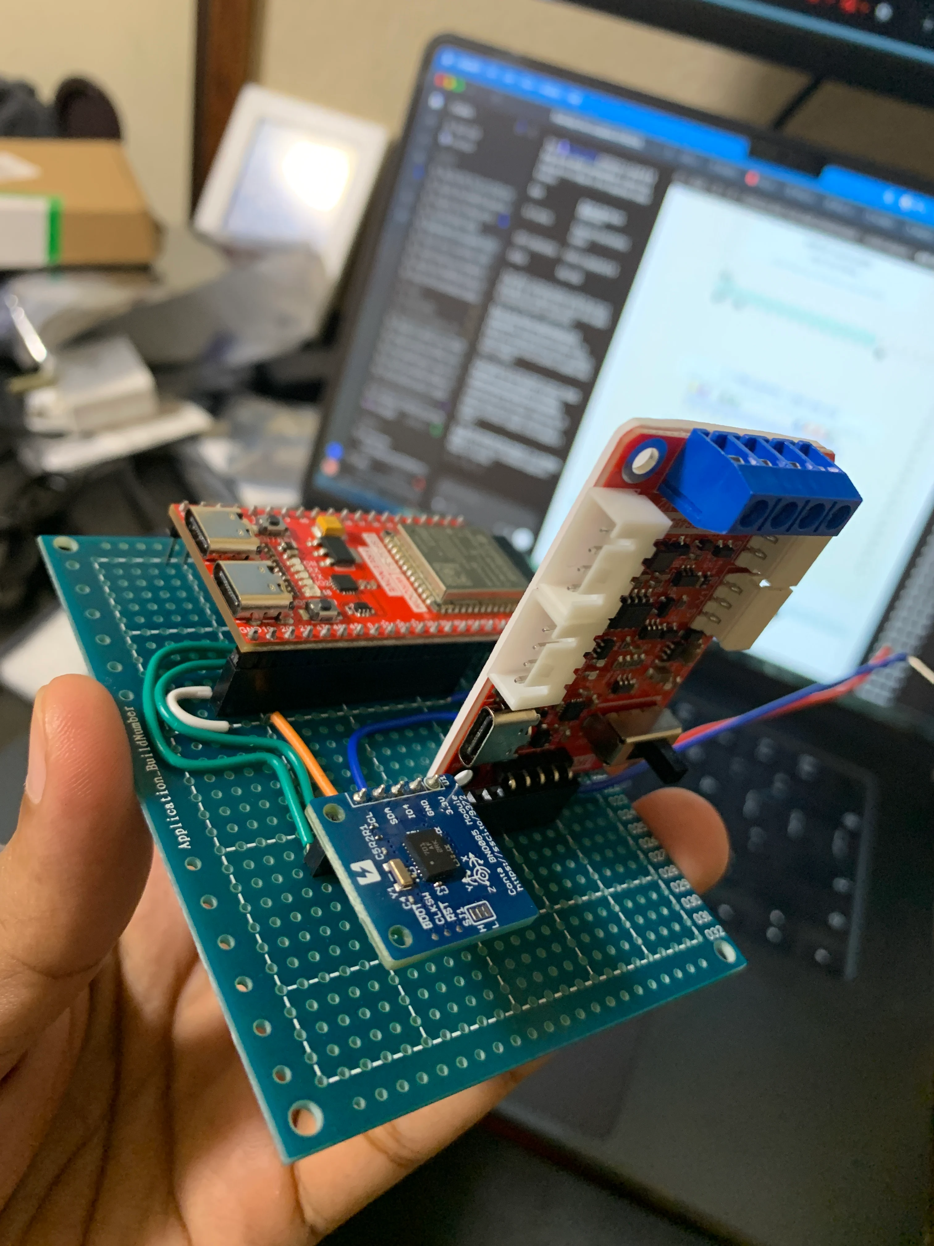
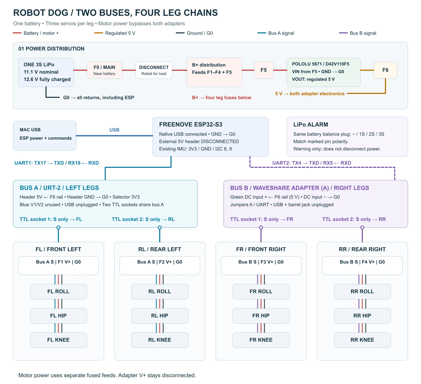
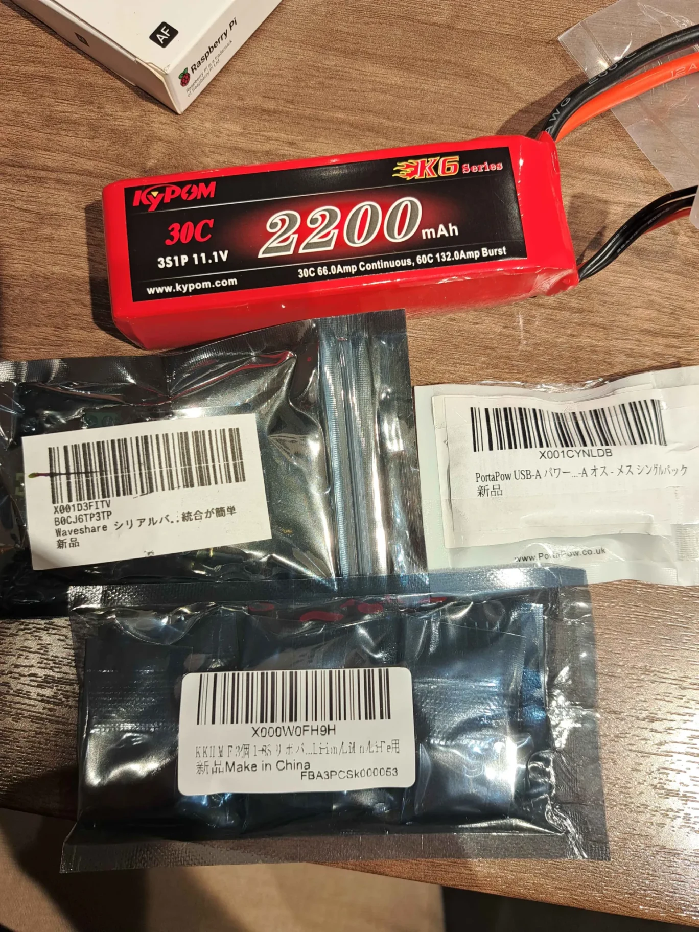
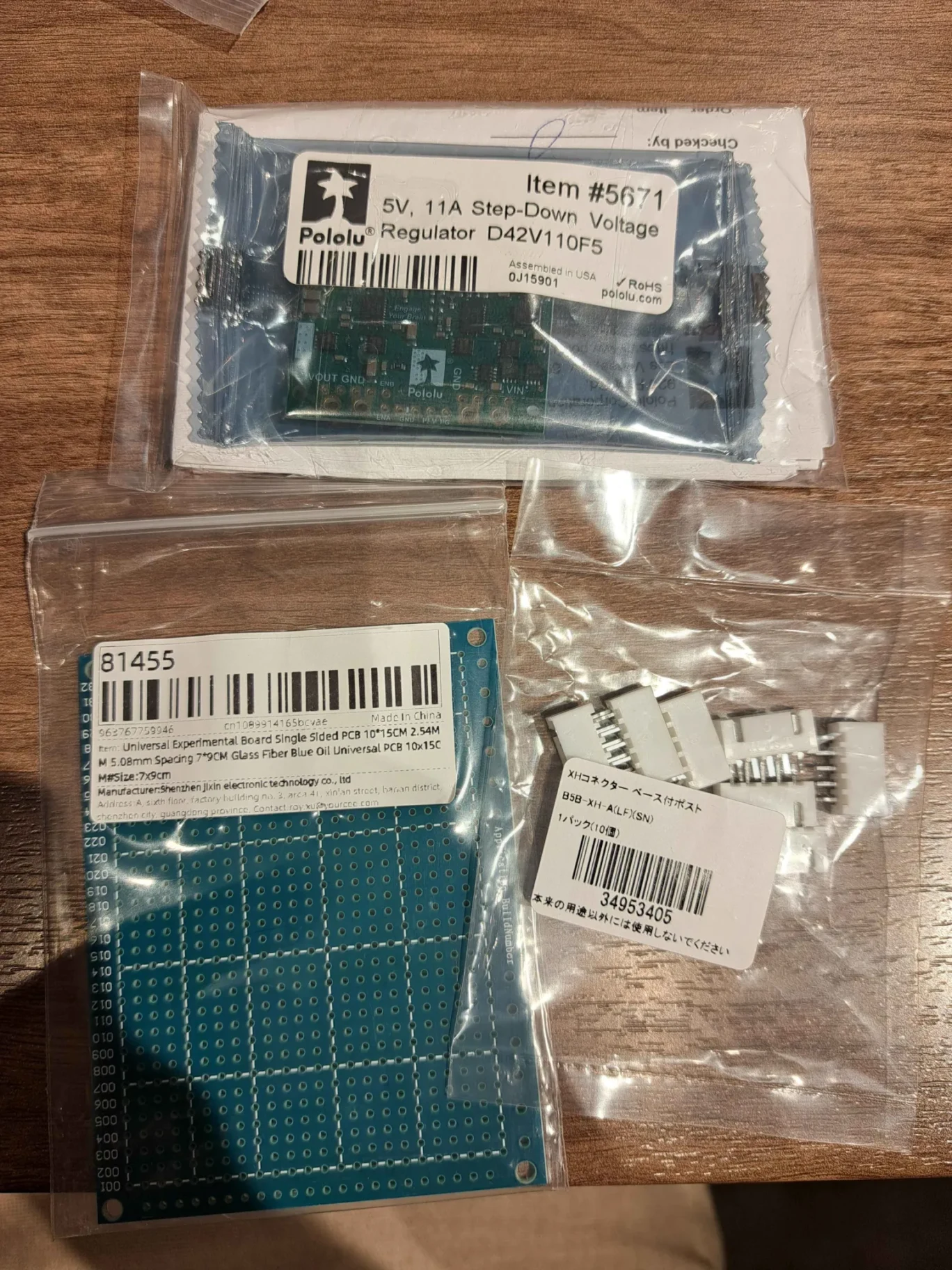
The original wiring proposal grouped the left and right legs. Later tests used the URT-2 adapter for the six rear motors and the Waveshare adapter for the six front motors. USB powered the ESP32, and a 3S battery powered the motors, with a common ground. The design included a 5 V regulator and fuse distribution; the final regulator connections, fuse ratings and return wiring were incompletely recorded.
Testing vision and distance sensing
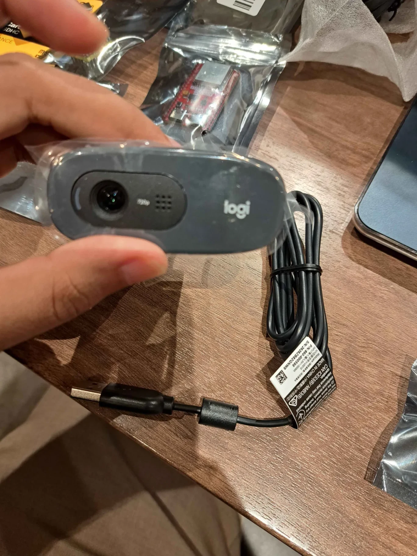
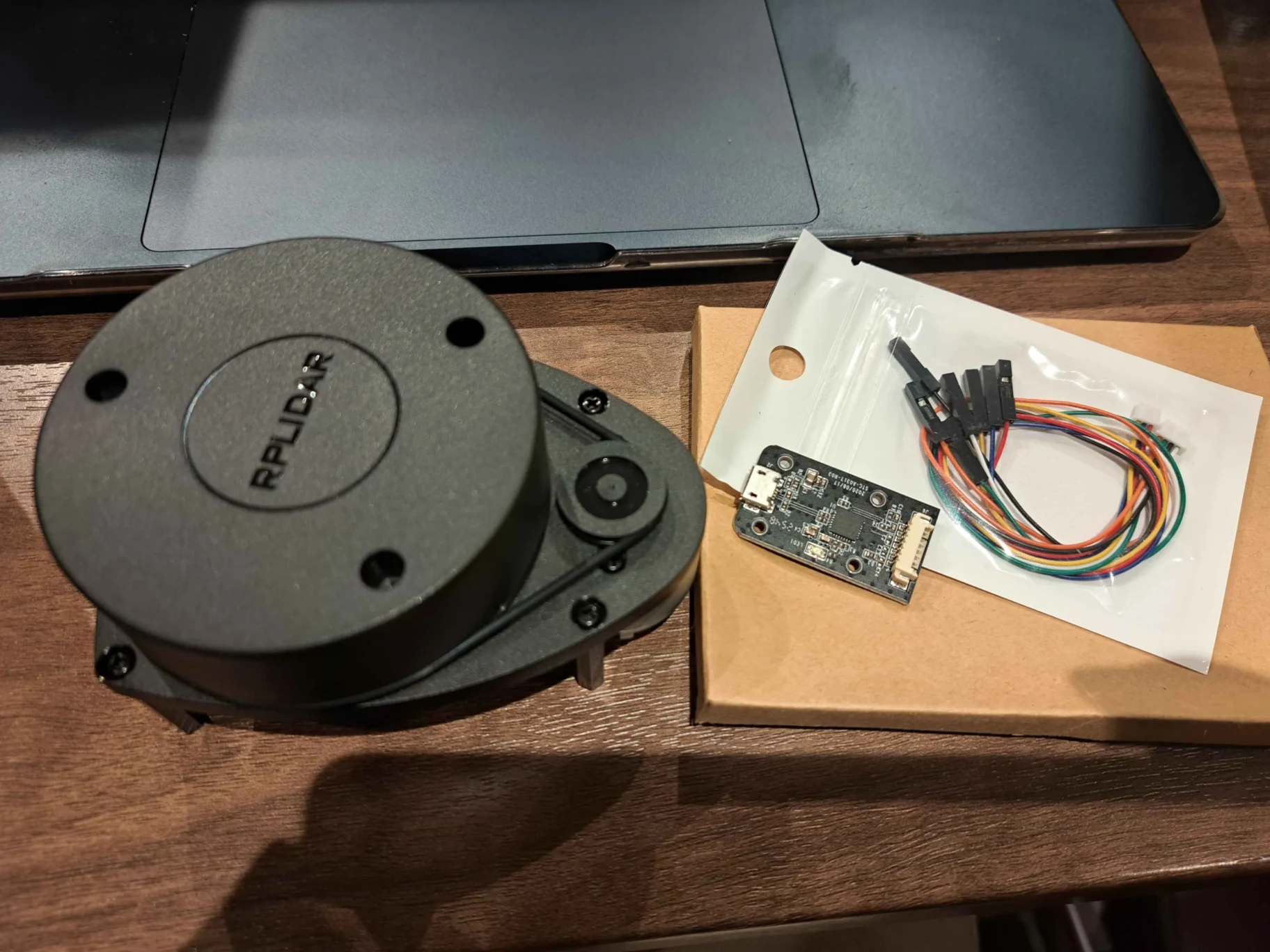
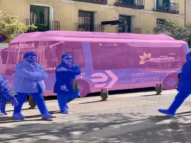
On a separate bench, we paired a YOLO object detector with a 2D LiDAR. The camera supplied object labels and the laser supplied ranges. Together they produced a live detection-and-distance view on the laptop.
We later added YOLO11n-seg to identify the pixels belonging to each detected object. Those outlines filter which laser points can contribute to its distance estimate. If too few laser points match, or they disagree about the distance, we leave the distance blank. The upgrade was tested on saved images and still needs a live comparison.
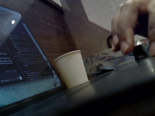
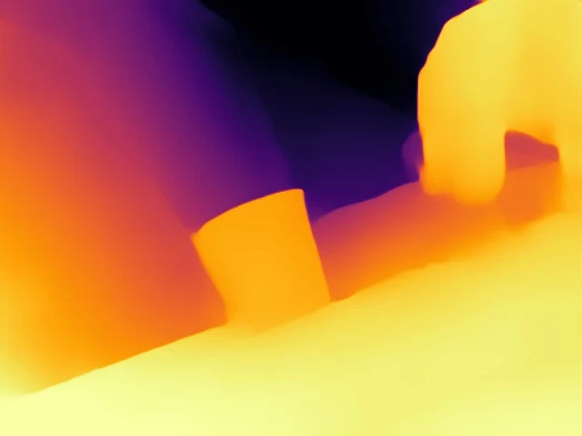
We also compared two models that estimate depth from a single camera frame. In the examples below, yellow areas are predicted nearer and dark areas farther away. Each model uses its own colour scale.

Separately, real laser scans supplied a local map of the room.
Capture settings mattered too. An alternative 1080p camera initially delivered around 5 frames per second. Selecting its intended format produced 297 decoded frames over 10.029 seconds, measured at about 29.5 fps. That improvement came before the images reached an AI model.
What comes next
We used Codex throughout the build to inspect reference code, develop software and prepare diagnostic tools. Physical observations decided which changes were useful. The next milestone is repeated four-leg cycles with observed foot placements, body movement and a stable finish. The command sequence has passed a desktop test using the controller’s message-reading and timing code.
Once walking is repeatable, we can compare the current planner with learned control: how closely does each follow a requested speed, and how reliably does it finish? We also want to try generating simpler movements on the board itself. Those comparisons need measurements of actual body movement and motor response under load. Perception can then be added to test whether seeing the ground ahead improves foot placement.
The results above come from the build records through October 30, 2026, 09:30 JST. Software benchmarks, calculated transmission times and short hardware checks answer different questions; none establishes a completed physical walking cycle.
Explore more of our work in VoicePing Research .