In this article
A 3D printer can make a part without someone standing beside it. Opening the enclosure and handling the next physical step still require a person. We’re adapting FORTE, an open robot-arm design, to investigate that gap—using Codex Astra to help develop the mechanics, simulation and checking tools.
Our first goal is printer access. Longer term, we want to explore physical interaction with other equipment, including servers. A useful starting point is one complete, measurable task.
A useful arm must complete the whole task
Reaching a point inside a printer is only part of operating it. The arm must also handle the door, clear the enclosure, withdraw and leave the machine ready for what follows. A base position that helps one motion may obstruct another.
Our prototype combines a six-joint arm, a gripper and an experimental sliding base. We have adapted CAD, simulated access sequences and initial printed parts. A fully assembled, powered arm operating the printer remains ahead. The experiments below help decide what is worth building and what must be measured next.
Commercial robot arms: Universal Robots, Franka and UFACTORY
Commercial platforms show different ways to approach manipulation. OpenArm adds an open-hardware option that also informed our build-versus-buy discussion.
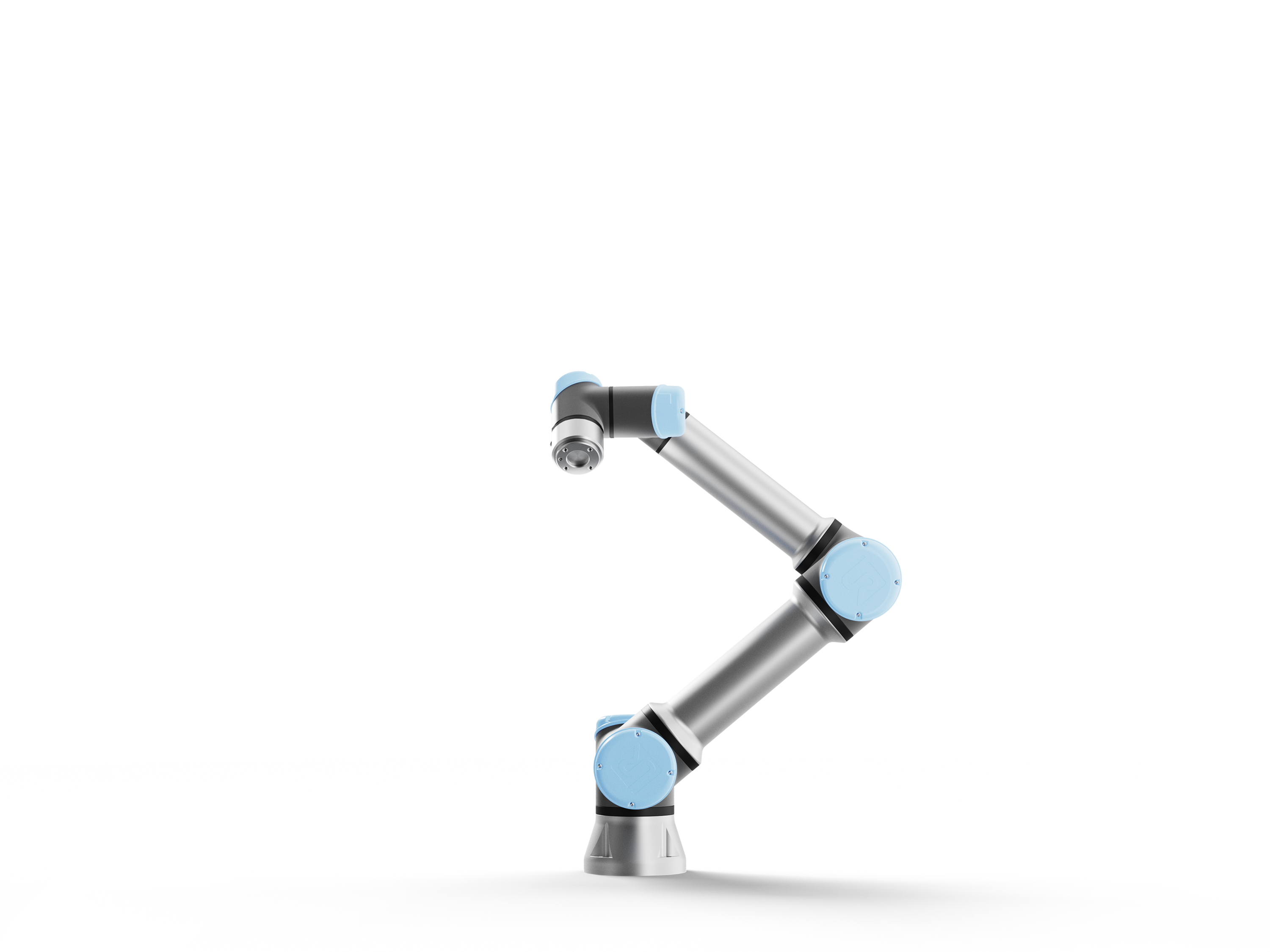
Integrate the whole task
Compact production arms with tool I/O, force sensing and a broad ecosystem of compatible components.
Research lens: The gripper, fixture and machine interface matter alongside the arm.
Image: Universal Robots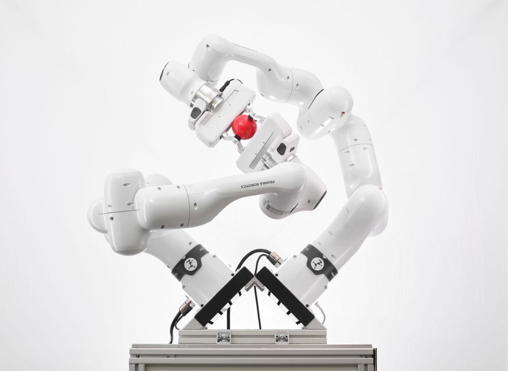
Understand contact
Seven joints with torque sensing and a 1 kHz interface for low-level control and measurements.
Research lens: Contact research needs observable forces and precise control access.
Image: Franka Robotics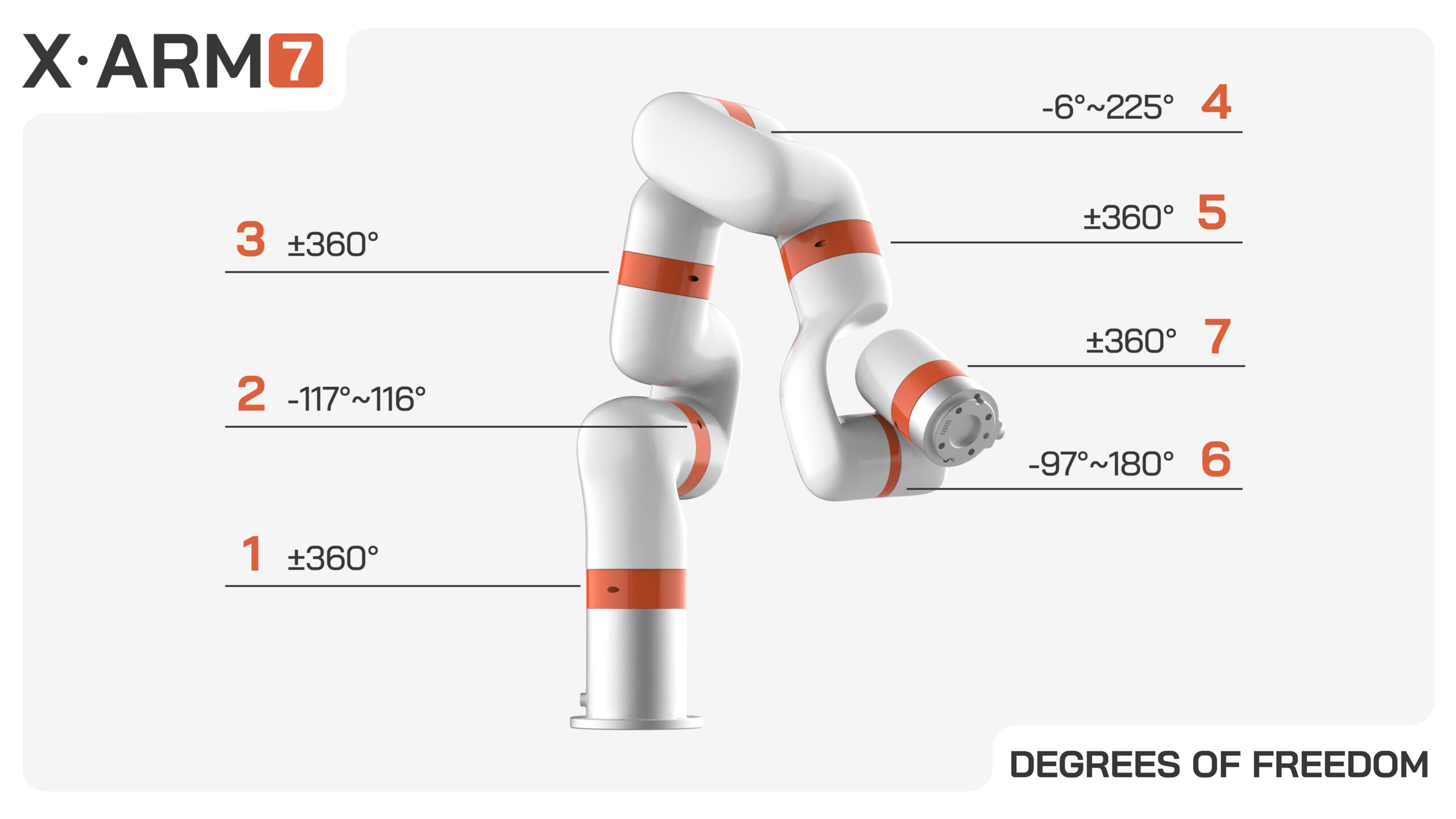
Access the software
Seven-axis arm with Python/C++ SDKs, ROS/ROS 2 packages and compatible gripper and linear-axis accessories.
Research lens: Check which interfaces the intended experiment actually needs.
Image: UFACTORY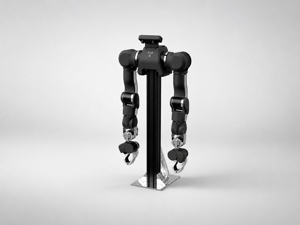
Build on open hardware
An open bimanual platform available assembled through manufacturing partners, with supplier-specific configurations and support.
Research lens: Separate experimental flexibility from assembly and qualification effort.
Image: WowRoboManufacturer imagery and specifications, checked September 24, 2026. Research lessons are our analysis; these are not hands-on comparisons.
Buying a platform can reduce mechanical integration work. Building FORTE gives us control over cable routes, mounts and geometry, while making us responsible for characterizing their behavior. That trade-off suits this experiment; it does not establish that a custom arm is the better production choice.
Our Place in the Robotics Market
Established robotics companies already provide capable arms, controllers and automation platforms. We want to contribute at the application level: turning robotic capability into practical tools for everyday operations, starting with 3D-printer handling and later interaction with other equipment.
Our aim is adaptable, cost-conscious automation. By combining open hardware, AI-assisted engineering and task-specific software, we want to make robots easier to tailor to the work around them. FORTE is an early step toward understanding how to make those systems useful, maintainable and economical in practice.
How the system fits together
The proposed hardware path is host computer → microcontroller and motor drivers → arm and gripper. A sliding base adds a second working position. Physical measurements of fit, joint response and contact will help calibrate the model.
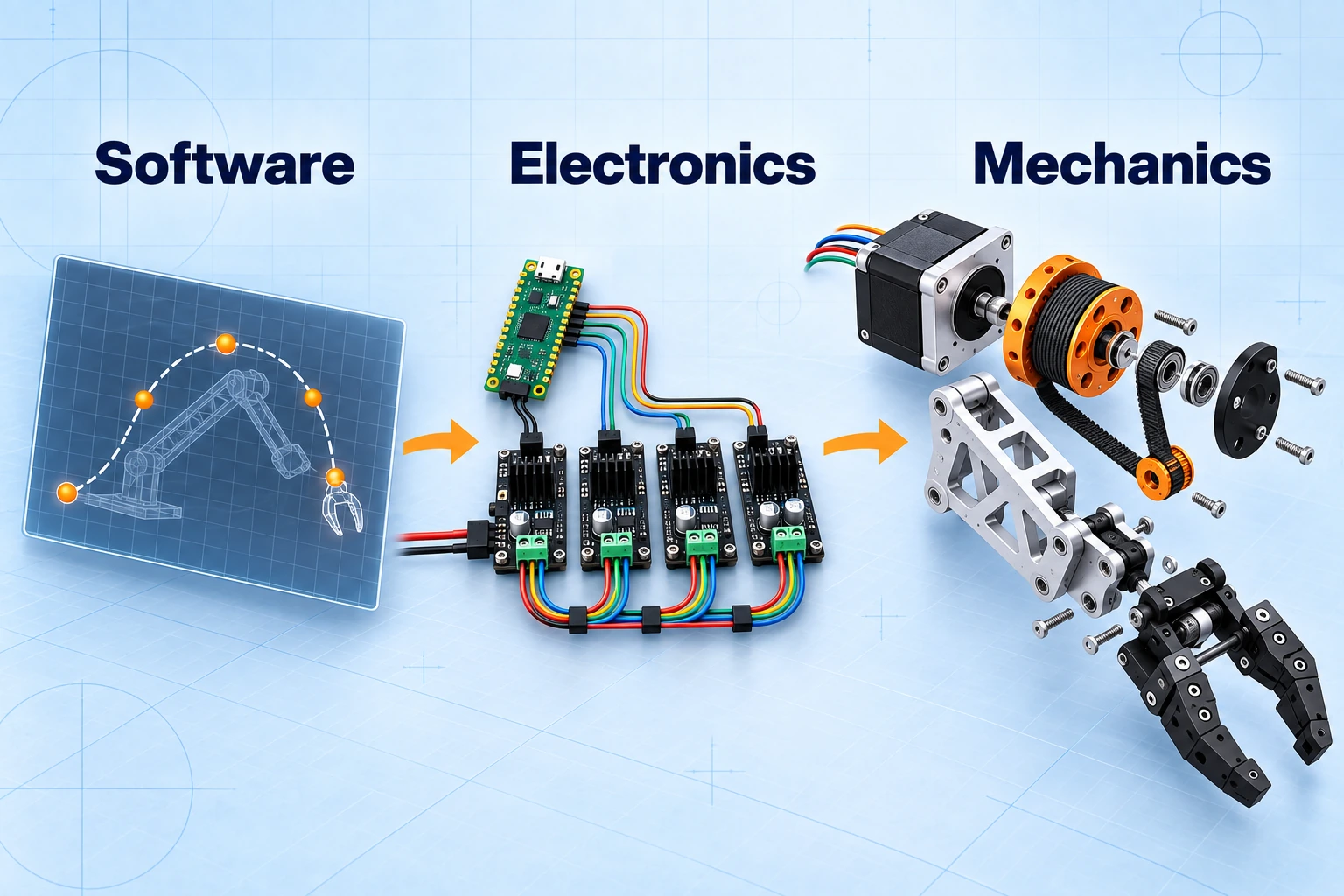
Today, motion runs in MuJoCo, where a controller issues actuator commands and the physics engine computes contact. Codex Astra supports development outside that control loop. Keeping these roles distinct lets us trace a failed motion to the geometry, controller or model assumptions.
How We’re Building It
We work through seven steps, returning to design when a test changes what we know.
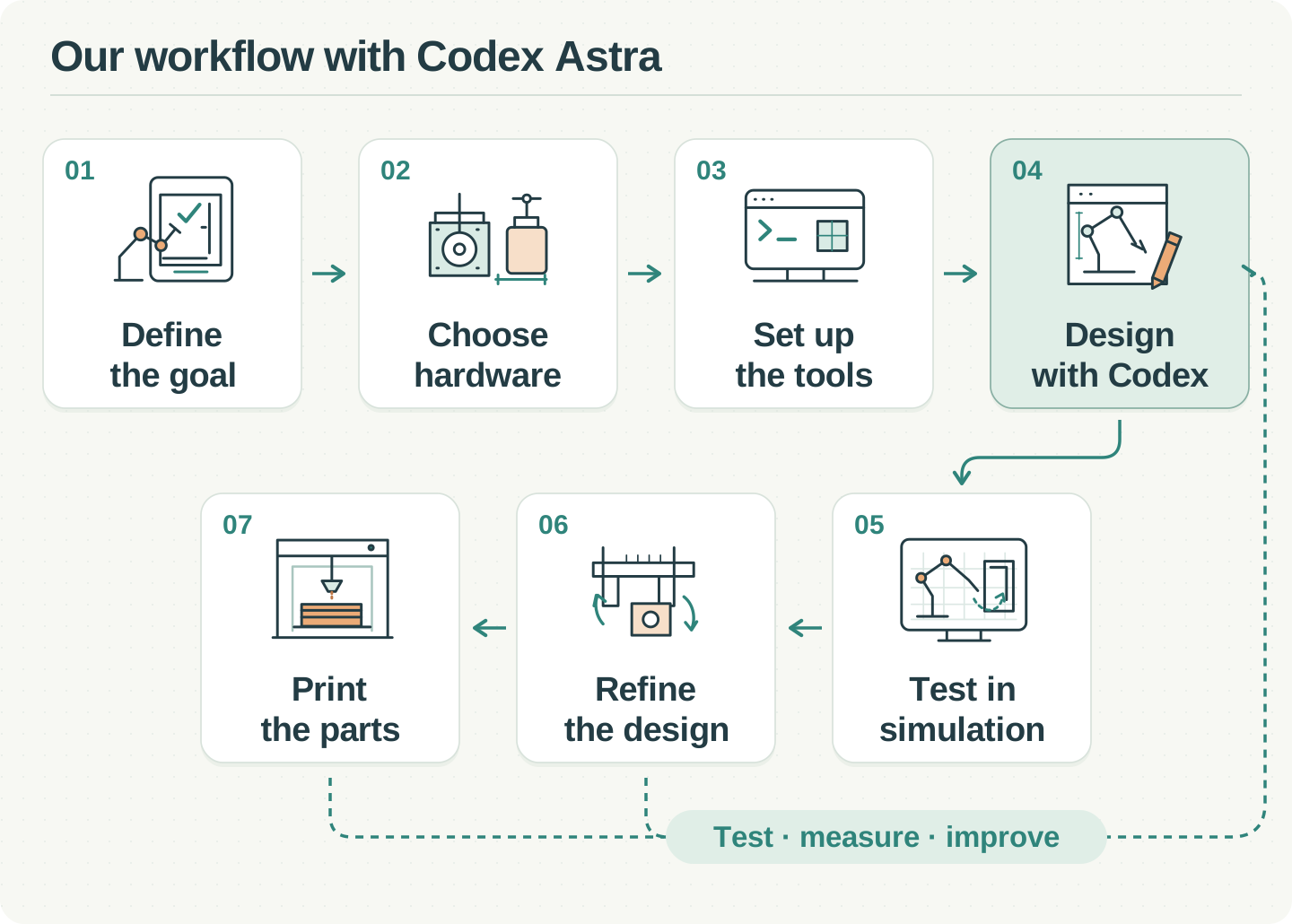
Defining the Goal
Our first sequence is open, reach, withdraw, close, with a 60-second cycle target. The upright arm must move the passive door through contact and avoid the enclosure. Reaching with an empty gripper tests access; removing a printed object requires a separate manipulation test.
Choosing the Hardware
FORTE’s paper and public repository provide printable structures, cable drives and timing belts we can modify. One early decision was to confirm exact motor models before approving CAD: identical frame sizes can hide different shafts and body lengths.
The planned electrical system connects the host laptop to a Pico 2, motor drivers and the gripper servo. Separating the signal and power paths makes the role of each selected component easier to inspect.
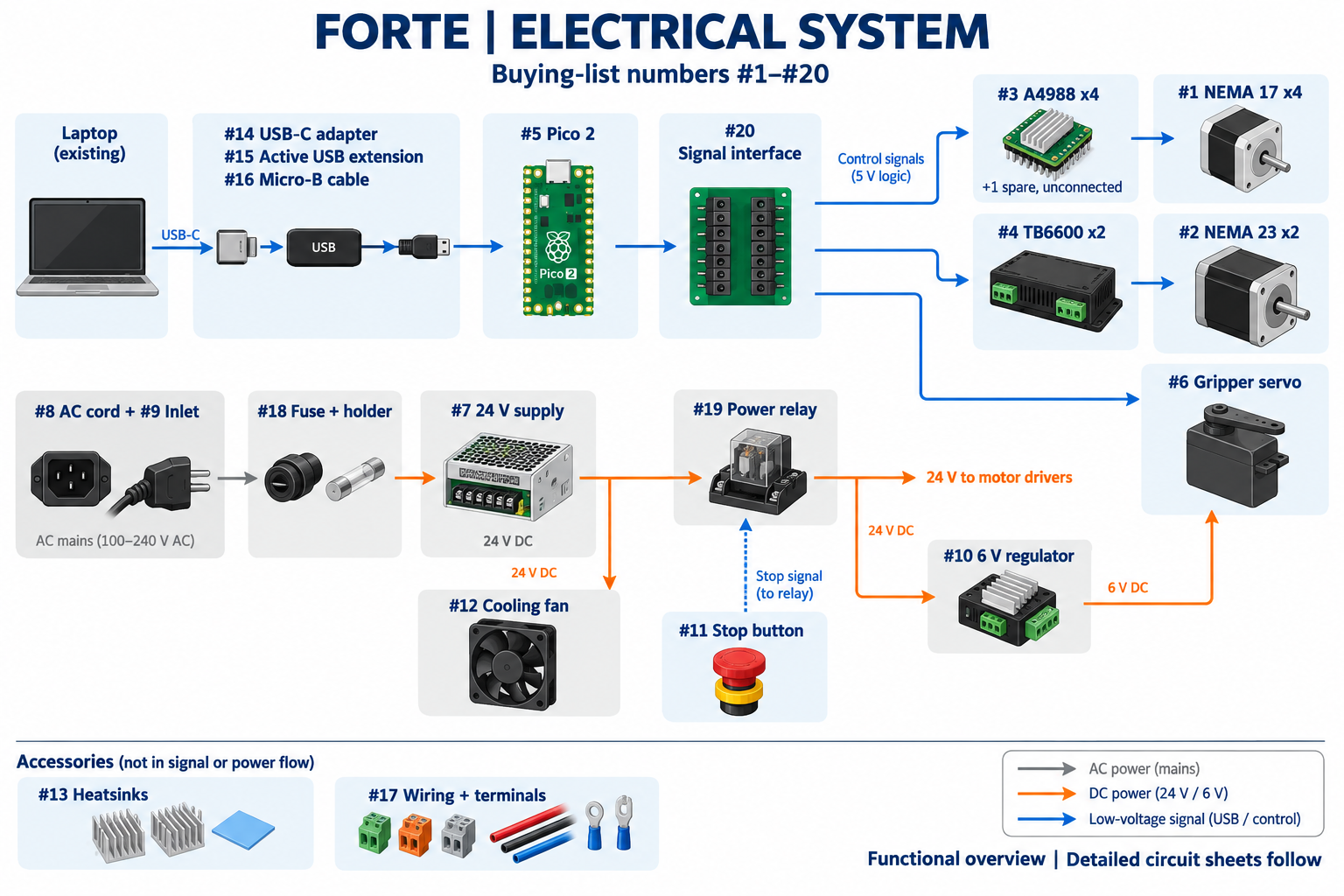
Our planned cash budget also reflects equipment we already own. OpenArm gives useful purchasing context, with a different configuration and level of readiness.
Our FORTE prototype
¥145,338
Planned cash, rounded
One arm; existing workshop equipment reused.
Engineering labor and rework are not priced.
OpenArm 2
US$6,500
Starting price · ≈¥1.04m at the planning exchange rate
A bimanual product; a different capability and configuration.
Configuration, freight and tax need a delivered Japan quote.
The FORTE estimate reuses our printer, laptop and workshop equipment; labor and rework are unpriced. OpenArm 2 is bimanual. Its starting price and supplier options need a delivered quote for a purchasing decision.
Inspect the arm CAD and selected motors (2)
4 × NEMA17
5 mm shafts; one double-shaft motor.
2 × NEMA23
Different shafts: 8 mm and 6.35 mm.
1 × gripper servo
DS3225, 270° variant.
The configuration uses four NEMA17 steppers, two NEMA23 steppers and a gripper servo. Shaft dimensions determine mounts and pulley fit; a Pico 2 and motor drivers are planned for the hardware interface.
Setting Up the Tools
The local environment runs on an Apple M5 Max with 128 GiB memory, using Python 3.11. MuJoCo handles CPU physics; PyTorch can use Apple’s MPS backend for training. Two experiment paths share one exclusive machine allocation: learned cube placement and scripted printer access.
Explore the simulation architecture and experiment pipeline (1)
Block-placement learning
- Prefect-managed environmentGymnasium ↔ MuJoCo · scripted demonstrations
- HDF5 → PyTorchTrajectories · training · saved policy
- Reserved simulation trialsPolicy + task sequencer + inverse kinematics
- MLflow + PostgreSQLRun history · metrics · artifact references
Printer-access research
- Bounded research launcherSource snapshot · shared allocation
- Contact controller ↔ MuJoCoActuator commands · passive door contact
- Cycle evaluationReach · contact · clearance · elapsed time
- Research output filesResults · traces · recorded replay
Reproducible execution. The simctl launcher snapshots source and task configuration. A Prefect worker verifies source hashes before running; simulation, training and the viewer share an exclusive allocation, with limits on memory, elapsed time, numerical threads and artifact size.
Learning path. Gymnasium wraps MuJoCo’s reset, observation, action and step interface. A scripted controller records demonstrations as HDF5 trajectories with timestamps and seeds. PyTorch trains a 16 → 128 → 128 → 4 behavioral-cloning network from an 80/20 split of 100 demonstrations. Inputs are normalized using only the training split, and validation loss selects the checkpoint. An explicit task sequencer and numerical inverse kinematics turn policy outputs into joint motion.
Reserved rollouts test task performance separately from training loss. MLflow with PostgreSQL tracking connects parameters and metrics to datasets, checkpoints and replays.
Printer path. A separate bounded launcher runs the scripted contact controller and writes research results and replay files. It shares the allocation, but does not register every run in MLflow. Actuator commands and MuJoCo contact move the passive door; no door motor or rigid gripper attachment forces the result.
Cable flex, backlash and complete self-collision remain outside the current model. FORTE’s public CAD , firmware and simulation are upstream references; our integrated experiment environment remains private.
Designing with Codex Astra
We give Codex Astra a specific mechanical problem, purchased hardware and acceptance checks. For the wrist, the important decision was to inspect both pulleys and the cable route together: a plausible individual part can still fail as a connected mechanism.
Design the mechanism, together
Inspect the part
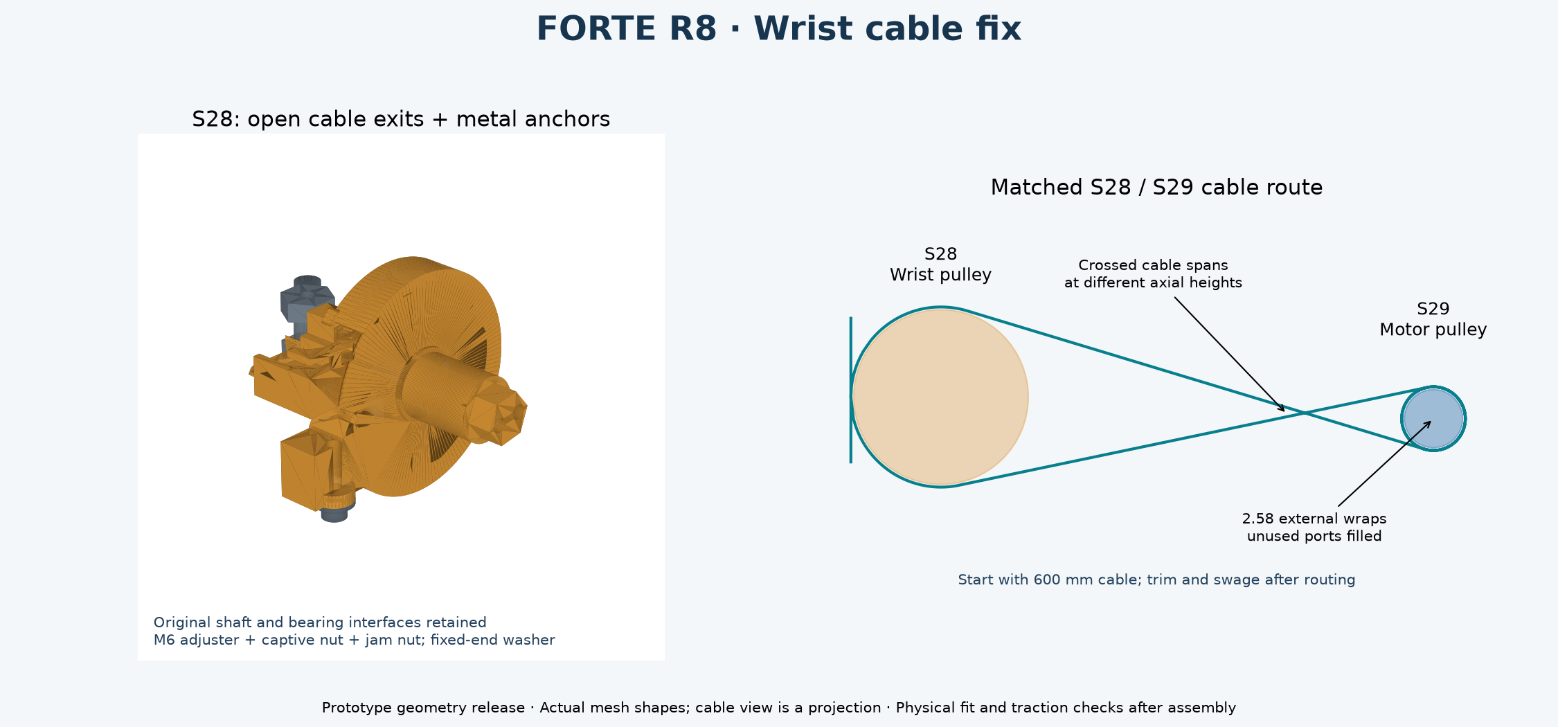
Cable outlets + anchors
Check the pair
Routing + winding direction
Specify
Motor dimensions, cable route and constraints.
Draft with Astra
CAD changes and scripts to inspect them.
Verify
Engineers check fit, load paths and access.
Codex Astra helps draft CAD changes and checking scripts. Engineers review fit, load paths and tool access before accepting them. The value is a shorter path from a proposed change to something we can inspect and test.
Testing in Simulation
A fixed base completed ten door-and-reach cycles in 58.18 simulated seconds each, but reached only 20 mm inside the assumed printable area. Moving closer improved interior reach while disrupting the complete door cycle.
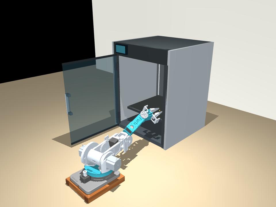
Door access, shallow reach
Tested target: 20 mm inside the assumed printable area.
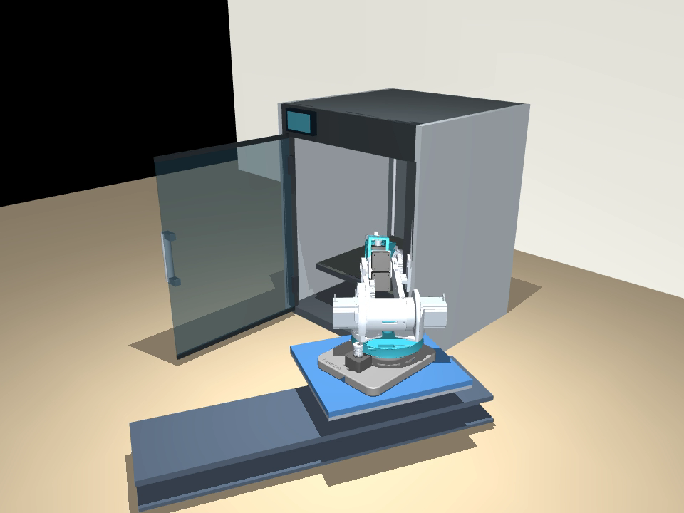
A second working position
A 360 mm stroke lets the empty gripper reach the assumed plate centre.
That trade-off motivated a 360 mm sliding base: one position for the door, another for interior access. The arm folds before moving inward, reaches the assumed plate centre, then reverses the sequence.
Refining the Design
The sliding base enables deeper reach, but the full cycle takes 190.02 simulated seconds, exceeding the 60-second target.
190.02 sSimulated cycle time
Centre reached · timing requirement not met
Folding, door handling and approach paths dominate the cycle. Improving rail speed alone would miss much of the delay. A sampled gap of roughly 0.45 mm also needs physical tolerance checks, and the simulated rail predates our latest CAD. Both issues must be resolved before transferring this motion to hardware.
Printing the Parts
We started with the turntable and prepared the remaining components in Bambu Studio. Recessed identifiers help connect similar-looking printed pieces to their assembly documentation.
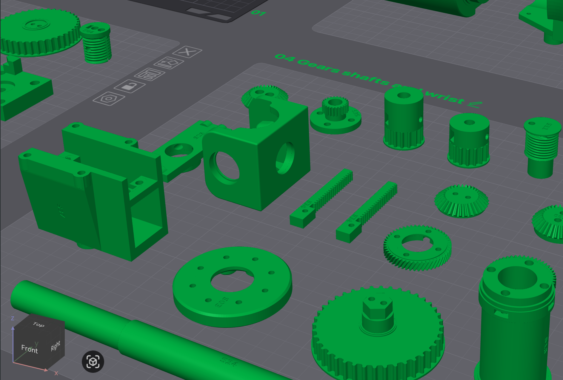
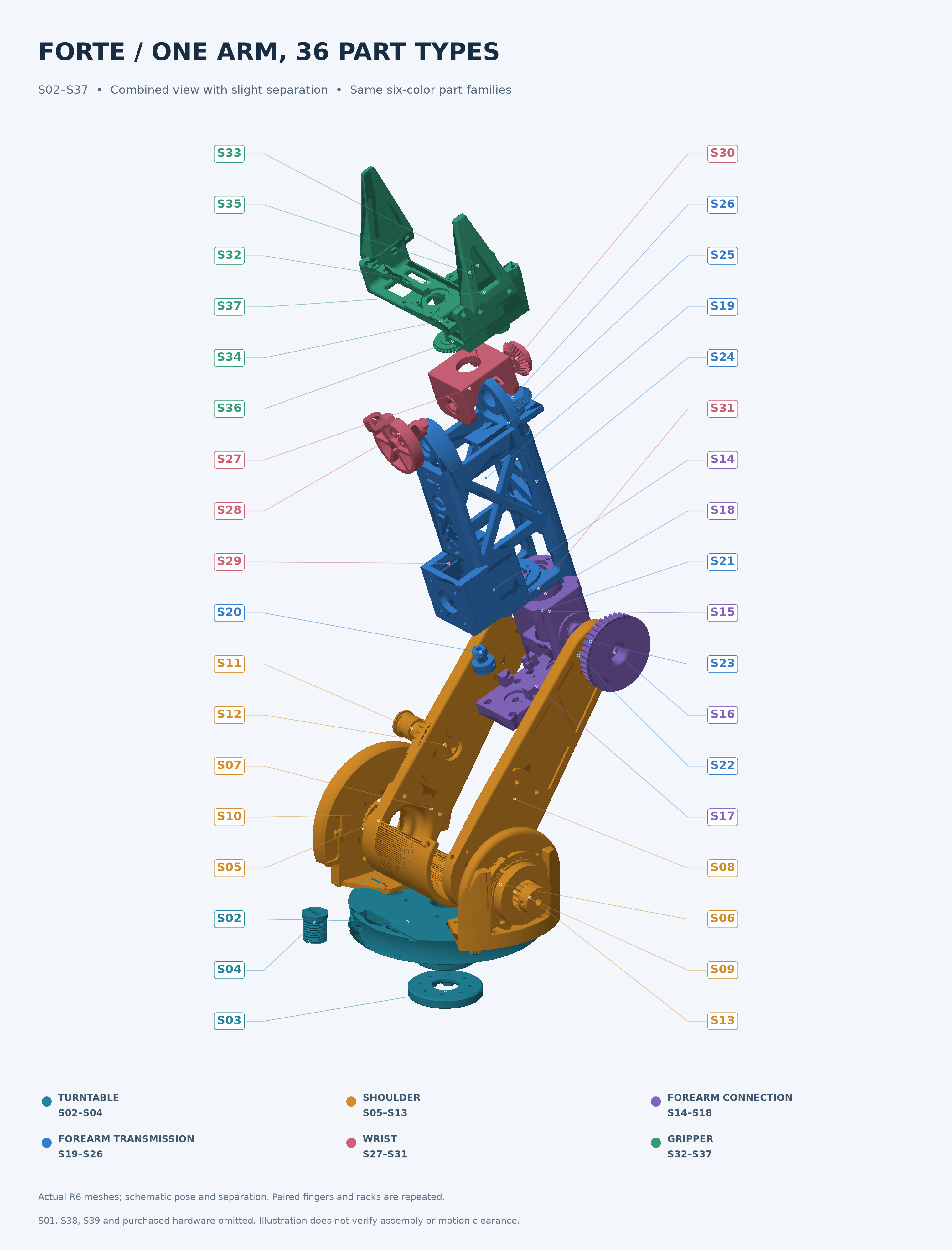
Identify every component
Part identifiers connect each component to the assembly documentation.
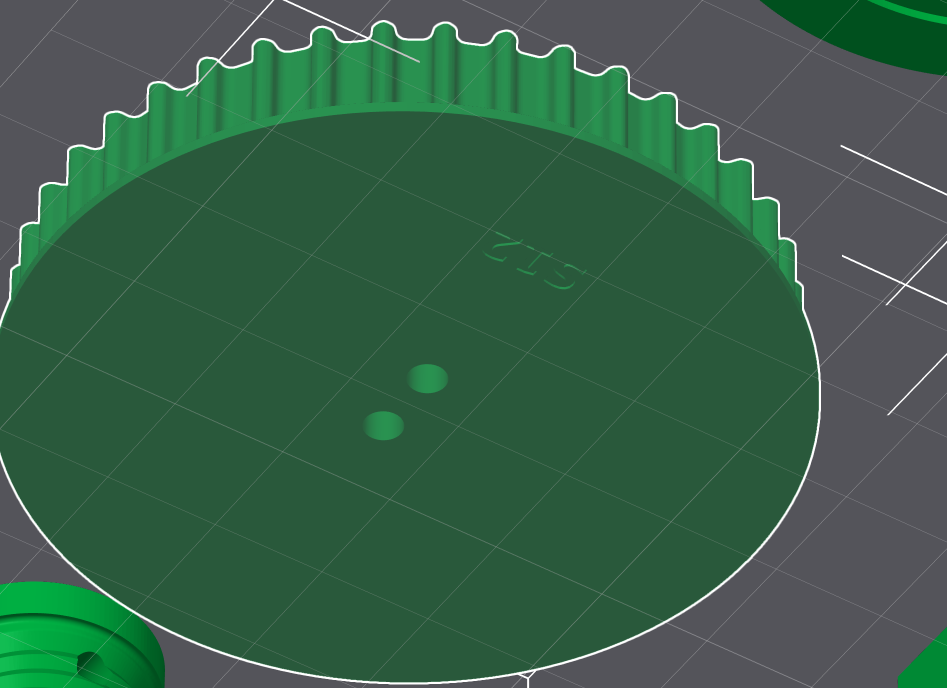
Carry the ID into the part
Recessed lettering stays with the component after it leaves the plate.
The remaining batch contains 35 designs / 37 pieces, estimated at 1.60 kg and 80 h 49 m under the selected PLA profile. Early bearing-seat and fastener-access checks can prevent a small fit error from causing another long print.
Simulation helps us learn across different conditions
Simulation lets us test one assumption at a time before changing hardware. For printer access, our next experiments would vary three conditions:
- Geometry: change the base position, door opening and target location to find where reach or clearance fails.
- Contact: vary door resistance and friction to test whether the gripper maintains useful contact.
- Position uncertainty: perturb the estimated target and joint positions to reveal motions that depend on unrealistically exact state.
We would first keep the controller fixed, record completion, unintended contacts and elapsed time, and reserve unseen combinations for evaluation. Physical measurements would then help set realistic variation ranges.
Our completed learning experiment is narrower. Behavioral cloning—learning actions from demonstrations—placed one 30 mm, 20 g cube successfully in 100 reserved trials, with 4.45 mm mean error. Starting positions varied by ±8 mm horizontally. This uses exact simulator state and an earlier arm model, rather than cameras or a learned printer policy.
The cube result validates a small learning-and-evaluation pipeline under those conditions. It does not yet establish robustness to door contact or perception error. Extending the tests will show which failures need a mechanical change, a controller adjustment or more demonstrations.
Research questions we want to investigate
Simulation to Physical Testing
The next milestone is assembly and powered testing of individual motions. We need measured joint response, cable tension, printer geometry and door resistance before attempting a complete access cycle.
The Open Engineering Questions
Which measurements make the simulator better predict physical behavior? We propose running the same printer-access controller in the initial simulator and a calibrated model, then comparing both predictions with held-out physical trials. Keeping the task and controller fixed helps isolate the value of calibration.
We would compare predicted and observed cycle completion, unintended contacts and elapsed time. Then, with the same tuning budget, we could develop a controller in each model and compare physical completion and human interventions under the same conditions. That separates better prediction from better control—and tests whether a faster motion remains dependable.
Where Future Teammates Can Contribute
There is concrete work in mechanism design, contact control, simulation calibration and perception. We’re looking for teammates who connect a proposed change to a repeatable experiment and a measurable result. Explore engineering opportunities at VoicePing .